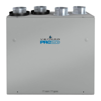
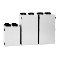
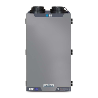
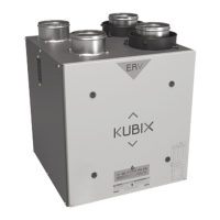
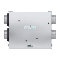
The Venmar AVS S10 ERV, S10 ERV ECM, S10c ERV, S10 ERVplus, S10n ERVplus, and vänEE 70E, 70E ECM, 70EC, 70E+, and 70EN+ units are residential energy recovery ventilators (ERVs) designed to improve indoor air quality by exhausting stale air and supplying fresh, filtered outdoor air. These units are suitable for various residential installations, including houses and high-rise dwellings, and can be integrated with forced air systems or operate as fully ducted independent systems.
Function Description:
These ERVs operate by continuously exchanging indoor stale air with fresh outdoor air. During this process, they recover energy (heat and humidity) from the exhausted air and transfer it to the incoming fresh air, reducing the energy load on the home's heating and cooling systems. The units are equipped with integrated balancing dampers to ensure proper airflow balance between the fresh air to building and exhaust air to outdoors ports. Some models feature integrated defrost controls to prevent ice buildup in colder climates, while others have integrated controls for basic operation. The units can be controlled by various main wall controls (e.g., Altitude, Deco-Touch, Lite-Touch Constructo, Simple-Touch Constructo, Platinum, Lite-Touch Bronze, Simple-Touch Bronze, or Constructo/Bronze) and optional auxiliary controls (e.g., Dehumidistat, 20/40/60-minute lighted push-button timer, and 60-minute crank timer).
Important Technical Specifications:
The units operate within an ambient temperature range of 18°C (65°F) and 40°C (104°F). They require a standard 3-prong electrical outlet within 3 feet of the unit. The power supply cord has a 3-prong grounding plug for safety. All unit ports are designed for a minimum 5" diameter duct connection, with the possibility of transitioning to larger ducts (e.g., 6" diameter) using appropriate adapters. Insulated flexible ducts are recommended for connections to exterior hoods and when ducts pass through unconditioned spaces.
Specific models (S10 ERV ECM and 70E ECM) offer three speed ranges with approximate CFM values:
- Speed Range 1 (Factory Set): 50 CFM (Min) to 105 CFM (Max)
- Speed Range 2: 65 CFM (Min) to 105 CFM (Max)
- Speed Range 3: 50 CFM (Min) to 85 CFM (Max)
For other units (except S10 ERV ECM and 70E ECM), the factory-set high speed is 100 CFM, and low speed is 50 CFM, adjustable by changing transformer wire taps.
Usage Features:
- Installation Methods: The manual outlines three primary installation methods: Fully Ducted System (for homes with radiant hot water or electric baseboard heating), Central Draw Point (connection to a forced air system), and Simplified Installation (connection to a forced air system). For high-rise dwellings, fully ducted and central draw point installations are also described.
- Ductwork Planning: Emphasizes keeping ductwork simple, minimizing bends and joints, and reducing the length of insulated ducts. It advises against ventilating crawl spaces or cold rooms and recovering exhaust air from dryers or range hoods to prevent filter clogging. For multi-level homes, at least one exhaust register at the highest lived-in level is recommended.
- External Hoods: Requires a minimum distance of 6 feet (1.8 m) between intake and exhaust hoods to prevent cross-contamination and 18 inches (457 mm) from the ground. An "Anti-gust intake hood" is suggested for snowy regions. A Tandem® transition kit (part no. 14690) can be used as an alternative to two exterior hoods, requiring a joist opening of at least 9¾" and a maximum height of 8¾".
- Booting Sequence: After being plugged in or following a power failure, the unit performs a booting sequence. During this time, the integrated control LED indicates the unit's status. No commands are taken until the unit is fully booted.
- Defrost Control (S10 ERVplus, S10n ERVplus, 70E+, 70EN+): These units have three defrost cycles:
- STANDARD (Factory Set): Most energy-efficient, performs defrost on high speed when needed.
- PLUS: For cold regions (-27°C [-17°F] and lower), performs defrost on high speed for a longer period.
- DISCRETION: Defrost speed matches the unit's ventilation speed (high or low).
The defrost cycle can be changed using a push button on the integrated control. A 15-minute delay is in place for the new setting to be saved.
- Integrated Control (S10 ERV, S10 ERV ECM, S10c ERV, 70E, 70E ECM, 70EC): These units use a push button on the integrated control to switch between low speed (AMBER LED), high speed (GREEN LED), or off/controlled by main control (NO LIGHT).
- Extended Defrost (S10 ERV, S10c ERV, 70E, 70EC): Factory-set to normal defrost, but can be set to extended defrost for colder regions. This setting is adjusted during the first 3 seconds of the booting sequence.
- Speed and Defrost Settings (S10 ERV ECM and 70E ECM): These models allow modification of speed ranges and defrost settings (Normal or Extended) through a specific procedure involving the integrated control push button during the booting sequence.
- Furnace Interlock: The units can be interlocked with a furnace blower for synchronized operation. Standard and alternate wiring methods are provided, especially for furnaces connected to cooling systems.
- Balancing: The units are balanced using a magnehelic gauge to measure airflow pressure. Integrated balancing dampers on the fresh air to building and exhaust air to outdoors ports are used to adjust airflow. The process involves setting the unit to high speed, ensuring all other exhaust devices are off, and adjusting dampers until airflow is balanced (within ±10 cfm).
Maintenance Features:
- Filter Cleaning: Users are advised to turn off the unit during construction or renovation to prevent premature filter clogging. Regular filter cleaning is essential for optimal performance.
- Annual Maintenance: The unit should be located in an area that allows easy access for quarterly and annual maintenance.
- Troubleshooting: A comprehensive troubleshooting guide is provided, detailing LED signals, error types, possible causes, and recommended actions. This includes checking electrical connections, replacing components like thermistors, motors, capacitors, or PCBs, and resetting the unit.
- Service Parts: A detailed list of service parts with corresponding part numbers and applicability to different models is included, ensuring that genuine replacement parts are used for optimal performance and safety.
Important Notes:
- Always disconnect power before servicing or making connections.
- Never use an electric screwdriver or drill when loosening or tightening damper lever locking screws.
- Ensure brackets are mounted to a solid surface (e.g., concrete ceiling, joists).
- The included screws are for wood joists only; do not use them for concrete or metal joists.
- Do not install stale air exhaust registers in closed rooms with combustion devices.
- Duct connections must comply with local building codes and safety regulations.
- If ducts pass through unconditioned spaces, they must be insulated.
- The vapor barrier on insulated ducts must not tear during installation to prevent condensation.
- Do not use screws to connect rigid ducts to the ports; use flexible duct lengths with tie-wraps and duct tape to avoid vibration.
- For optimal performance, the furnace/air handler blower should always be ON during simplified installation (Method 2).
- If using an optional auxiliary wall control, its activation will override main wall control commands.