9
2. INSTALLATION (CONT’D)
2.6 INSTALLING THE DUCTWORK AND REGISTERS (CONT’D)
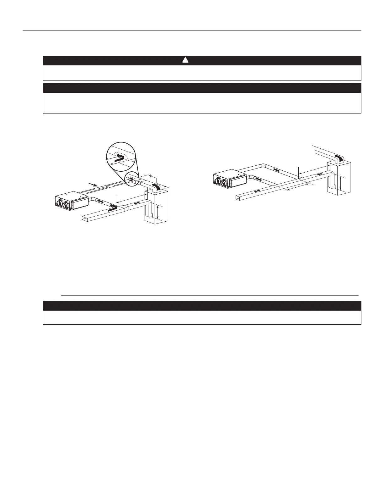
2.6.3 SIMPLIFIED INSTALLATION (AS ILLUSTRATED IN SECTION 1.1.3)
There are 2 methods for connecting the unit to the furnace/air handler:
Stale air intake:
• Cut an opening into the furnace/air handler return duct not less than 10 feet (3.1 m) from the furnace/air handler (A+B).
• Connect this opening to the Exhaust air from building port of the ERV.
Fresh air distribution:
• Same instructions as for Method 1 or Method 2, Section 2.6.2.
For Method 2 (Return-return), make sure there is a distance of at least 3 feet (0.9 m) between the 2 connections to the furnace/
air handler.
NOTE: For Method 1, it is not essential to synchronize the furnace blower operation with the unit operation, but we recommend it.
CAUTION
When performing duct connections to the furnace supply duct, this duct must be sized to support the additional
airflow produced by the ERV. Also, use a steel duct. For a Return-Return installation, the furnace blower must be in
operation when the ERV is in operation.
VJ0115
B
A
VJ0114
B
A
STEEL DUCT
MINIMUM 18"
(0.5 M)
A+B=
NOT LESS
THAN 10' (3.1 M)
M
INIMUM 3'
(0.9 M)
A+B=
NOT LESS
THAN 10' (3.1 M)
CAUTION
If using Method 2, make sure the furnace/air handler blower operation is synchronized with the unit operation! See
Section 4.
WARNING
When performing duct connections, always use approved tools and materials. Respect all corresponding laws and
safety regulations. Please refer to your local building code.
!
Method 1: Supply-return connection (All units)
Method 2: Return-return (exclusively for
AVS S10 ERVplus, AVS S10n ERVplus, 70E+
and 70EN+ units)