8
2. INSTALLATION (CONT’D)
2.5 PLANNING OF THE DUCTWORK
• Keep it simple. Plan for a minimum of bends and joints.
• Keep the length of insulated ducts to a minimum.
• Do not ventilate crawl spaces or cold rooms. Do not attempt to recover the exhaust air from a dryer or a range hood. This would
cause clogging of the filters and recovery module.
• If the house has two floors or more, be sure to plan for at least one exhaust register on the highest lived-in level.
2.6 INSTALLING THE DUCTWORK AND REGISTERS
2.6.1 FULLY DUCTED SYSTEM (AS ILLUSTRATED IN SECTIONS 1.1.1 AND 1.2.1)
Stale air exhaust ductwork:
• Install the stale air exhaust registers where the contaminants are produced: kitchen, living room, etc. Position the registers as far
from the stairway as possible and in such a way that the air circulates in all the lived-in spaces in the house.
• If a register is installed in the kitchen, it must be located at least 4 feet (1.2 m) from the range.
• Install the registers 6 to 12 inches (152 to 305 mm) from the ceiling on an interior wall OR install them in the ceiling.
Fresh air distribution ductwork:
• Install the fresh air distribution registers in bedrooms, dining rooms, living room and basement.
• Keep in mind that the fresh air registers must be located as far as possible from the stale air registers.
• Install the registers in the ceiling OR 6 to 12 inches (152 to 305 mm) from the ceiling on an interior wall.
• If a register must be floor installed, direct the airflow up the wall.
WARNING
Never install a stale air exhaust register in a closed room where a combustion device operates, such as a gas furnace,
a gas water heater or a fireplace.
!
2.6.2 CENTRAL DRAW POINT SYSTEM (AS ILLUSTRATED IN SECTIONS 1.1.2 AND 1.2.2)
Stale air exhaust ductwork:
Same as for Fully Ducted System, described on point 2.6.1
Fresh air distribution ductwork:
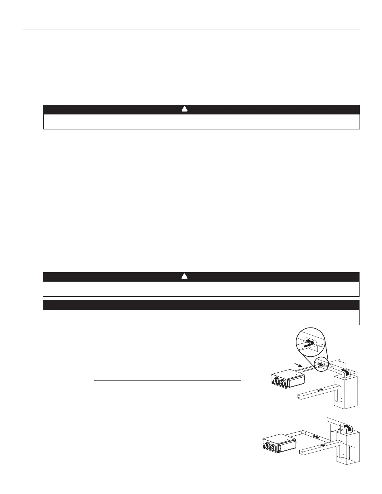
There are 2 methods for connecting the unit to the furnace/air handler:
Method 1: Supply side connection (All units)
• Cut an opening into the furnace supply duct at least 18 inches (0.5 m) from the furnace/air
handler.
• Connect this opening to the Fresh air to building port of the ERV (use steel duct, see
figure at right).
• Make sure the ERV duct forms an elbow inside the furnace/air handler ductwork.
• If desired, interlock (synchronize) the furnace/air handler blower operation (see Section 4).
Method 2: Return side connection (exclusively for AVS S10 ERVplus, S10n ERVplus,
70E+ and 70E
N+ units only)
• Cut an opening into the furnace return duct not less than 10 feet (3.1 m) from the
furnace/air handler (A+B).
• Connect this opening to the Fresh air to building port of the ERV (see figure at right).
NOTE: For Method 2, it is not essential that the furnace/air handler runs when the unit
is in operation, but we recommend it. If desired, interlock (synchronize) the
furnace/air handler blower operation (see Section 4).
WARNING
When performing duct connections, always use approved tools and materials. Respect all corresponding laws and
safety regulations. Please refer to your local building code.
!
CAUTION
When performing duct connections to the furnace supply duct, this duct must be sized to support the additional
airflow produced by the ERV. Also, use a steel duct.
VJ0112
STEEL DUCT
MINIMUM 18"
(0.5 M)
B
A
VJ0113
A+B= NOT LESS
THAN 10' (3.1 M)