5
1. TYPICAL INSTALLATIONS (CONT'D)
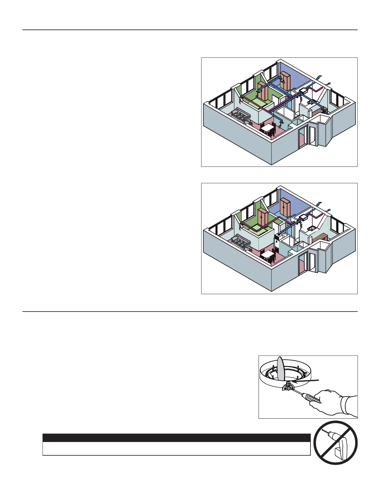
1.2.1 FULLY DUCTED SYSTEM (PRIMARILY FOR HOMES WITH RADIANT HOT WATER OR ELECTRIC BASEBOARD HEATING)
1.2 FOR HIGH-RISE DWELLING
Stale air coming from the registers located in bathrooms and
kitchen is exhausted to the outside. Fresh air from outside is
filtered and supplied by the registers located in bedrooms and
living room.
See figure at right.
VH0095
1.2.2 CENTRAL DRAW POINT (CONNECTION TO A FAN-COIL SYSTEM)
Stale air coming from the registers located in bathrooms and
kitchen is exhausted to the outside. Fresh air from outside is
filtered and supplied to the supply duct of the fan-coil system
unit. See figure at right.
For this type of installation, it is not essential that the fan-coil
system blower runs when the unit is in operation, but we
recommend it.
VH0094
2. INSTALLATION
2.1 INSPECT THE CONTENTS OF THE BOX
• Inspect the exterior of the unit for shipping damage. Ensure that there is no damage to the door, door hinges, power cord, etc.
• Open the unit door and inspect the interior of the unit for damage. Ensure that energy recovery core, core filters, insulation,
dampers, etc. are all intact.
2.2 UNIT PREPARATION
All units are equipped with 2 ports having integrated balancing damper (Fresh air to
building and Exhaust air to outdoors ports). Before installing the unit, check if these
2 ports are in wide open position. If not, proceed as follow:
Loosen the damper lever locking screw.
Use the damper lever to open the damper.
Lock the damper in position by tightening the locking screw.
DAMPER LEVER
CAUTION
When loosing or tightening the damper lever locking screw, never use an electric screwdriver or drill,
use a standard screwdriver.