- 19 -
Appendix H
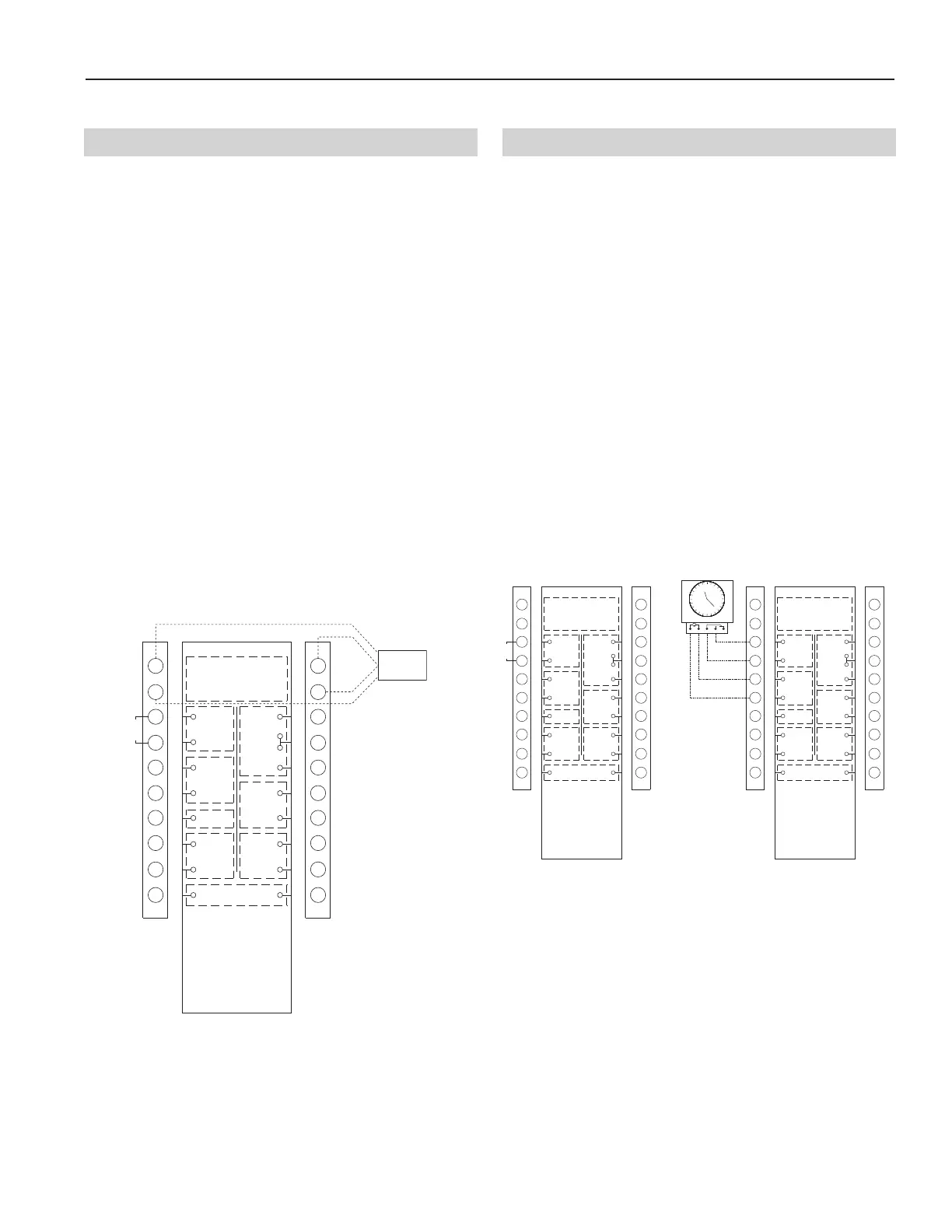
Terminal Control Diagrams
Two types of remote wall controls are available:
1. Standard Wall Control with fan switch and dehu-
midistat control.
2. Xtra Wall Control with fan mode selection, dehu-
midistat control and maintenance indicator.
The remote wall controls work with the integrated elec-
tronic controls within the unit to control ventilation
sequences. Each wall control above has different fea-
tures and requires 4-wire connection to the unit as shown
below. Without the wall control, fans can be operated
with dry contacts or a switch as in control diagram H-4.
NOTE: All controls accessories (Ex. Night setback timer,
CO
2
controller, enthalpy controller, smoke detec-
tor or wheel rotation sensor) intended to provide
a contact closure for occupancy control across
terminals 3 and 4 cannot be used in conjunction
with the Xtra wall control.
If a wall control is required in addition to any of
these options, only the Standard wall control
may be used. Without these options, a factory
installed jumper across terminals 3 and 4 must
be installed.
Occupancy control is achieved by connection to the ter-
minal interface shown below. These terminals require a
dry contact which could be provided by a number of types
of controls such as a timer, light sensor, occupancy sen-
sor, building management system or other. The unit will
not operate unless these contacts are closed!!
The drawing below shows a factory installed jumper
and programmable timer option.
NOTE: All controls accessories (Ex. Night setback timer,
CO
2
controller, enthalpy controller, smoke detec-
tor or wheel rotation sensor) intended to provide
a contact closure for occupancy control across
terminals 3 and 4 cannot be used in conjunction
with the Xtra wall control.
If a wall control is required in addition to any of
these options, only the Standard wall control
may be used. Without these options, a factory
installed jumper across terminals 3 and 4 must
be installed.
H-1: Wall Control Connection H-2: Occupied Timer/Sensor Connection
Wall
Control
CONTROL CONTACTS
CLASS 2 VOLTAGE
WALL CONTROL
BLACK
1
2
3
4
5
6
7
8
9
10
11
12
13
14
15
16
17
18
19
20
NOTE:
Connections are all dry contacts
except wall control, wheel alarm
contacts and 24 VAC power contacts.
Use of 24 VAC circuit requires
isolating contacts (ex. thermostat)
to prevent interconnection of
Class 2 outputs.
RED
OCCUPIED
TIMER/
SENSOR
FIELD WIRED
TERMINALS
AB
UNOCC.
RECIRC
CONTACTS
LOW
COMMON
HIGH
D
IRTY
FILTER
INDICATOR
(1.5A-24 VAC)
(
ERV UNITS)
WHEEL
ALARM
OPTION
(24 VAC)
(
ERV UNITS)
ENTHALPY
(-) 24 VAC
(40 VA)
(+) 24 VAC
GREEN
YELLOW
(RECIRC UNITS)
JUMPER
JUMPER
(factory installed)
OCCUPANCY CONTROL
(field installed)
NSB Timer
1
M
2345
JUMPER
CONTROL CONTACTS
CLASS 2 VOLTAGE
WALL CONTROL
BLACK
1
2
3
4
5
6
7
8
9
10
11
12
13
14
15
16
17
18
19
20
NOTE:
C
onnections are all dry contacts
except wall control, wheel alarm
contacts and 24 VAC power contacts.
Use of 24 VAC circuit requires
isolating contacts (ex. thermostat)
to prevent interconnection of
C
lass 2 outputs.
RED
O
CCUPIED
TIMER/
S
ENSOR
F
IELD WIRED
TERMINALS
AB
UNOCC.
RECIRC
CONTACTS
LOW
COMMON
HIGH
DIRTY
FILTER
INDICATOR
(
1.5A-24 VAC)
(
ERV UNITS)
WHEEL
A
LARM
OPTION
(24 VAC)
(ERV UNITS)
E
NTHALPY
(-) 24 VAC
(
40 VA)
(+) 24 VAC
GREEN
YELLOW
(
RECIRC UNITS)