- 4-
Make Duct Connections
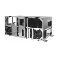
ERV500i
Port locations for the indoor unit are labeled in
Appendix B-1.
An 18" [457mm] long section of straight duct must be
used immediately after the supply fan to achieve optimal
fan performance. Transitions (field supplied) may be
required to make connection with ductwork that is
properly sized for minimum noise and pressure loss. Both
duct connections to outside must be insulated to avoid
condensation and heat loss. A continuous integral vapor
barrier must be used over the duct insulation.
Airflow rate balancing dampers are recommended for
both supply and exhaust ducts to allow for adjustment of
airflows as shown in Appendix D-1. Flexible connectors
should be installed close to the unit in the duct leading to
occupied spaces to minimize noise transmission. All ports
have 1" [25mm] flanges to facilitate duct connection.
Ensure that fasteners used to make duct connection
do not interfere with fans or dampers in the unit.
Electric preheat, if used as frost control, must be
installed in the intake from outside at a minimum distance
from the unit port of 24" [610mm].
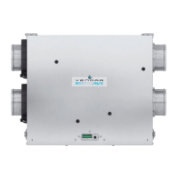
ERV500e
On vertical discharge units, secure all ducts to the
roofcurb and building structure. Do not secure ductwork
to the unit. For duct size requirements, see Appendix B.
Insulate and weatherproof all external ductwork, joints
and roof openings with counter flashing and mastic in
accordance with applicable codes. Ductwork running
through roof decks must comply with local fire codes.
Ducts passing through unconditioned spaces must be
insulated and covered with a vapor barrier. Flexible
connectors should be installed close to the unit in
the duct leading to occupied spaces to minimize noise
transmission.
Rigging And Placing The Unit (ERV500e ONLY)
Inspect the exterior and interior of the equipment for
damage. Ensure there is no damage to internal compo-
nents such as fans, motors, dampers, enthalpy wheel,
insulation and structures. File a claim with the shipping
company if the unit is damaged.
Spreader bars are required to prevent damage to the
roof flange. Rollers may be used to move the unit across
a roof. Lifting holes are provided in the base rails as shown
in Appendix C. For weights and overall dimensions, see
Appendix B-2.
Location
Maintain clearance around and above the unit to pro-
vide proper airflow and service access. The fresh air
intake hood must be positioned away from sources of
contamination such as chimneys, exhaust vents, etc.
Positioning the fresh air intake opposite to the prevailing
winds will reduce entry of snow or moisture during periods
of high winds.
Install Hoods (ERV500e ONLY)
Intake and exhaust hoods for these models are shipped
separately from the unit. See Appendix C for hood installa-
tion information. A quick connect for the damper motors is
provided to connect to the main body of the unit. Make
sure that all screws are secured to maintain proper support
and keep seals watertight.
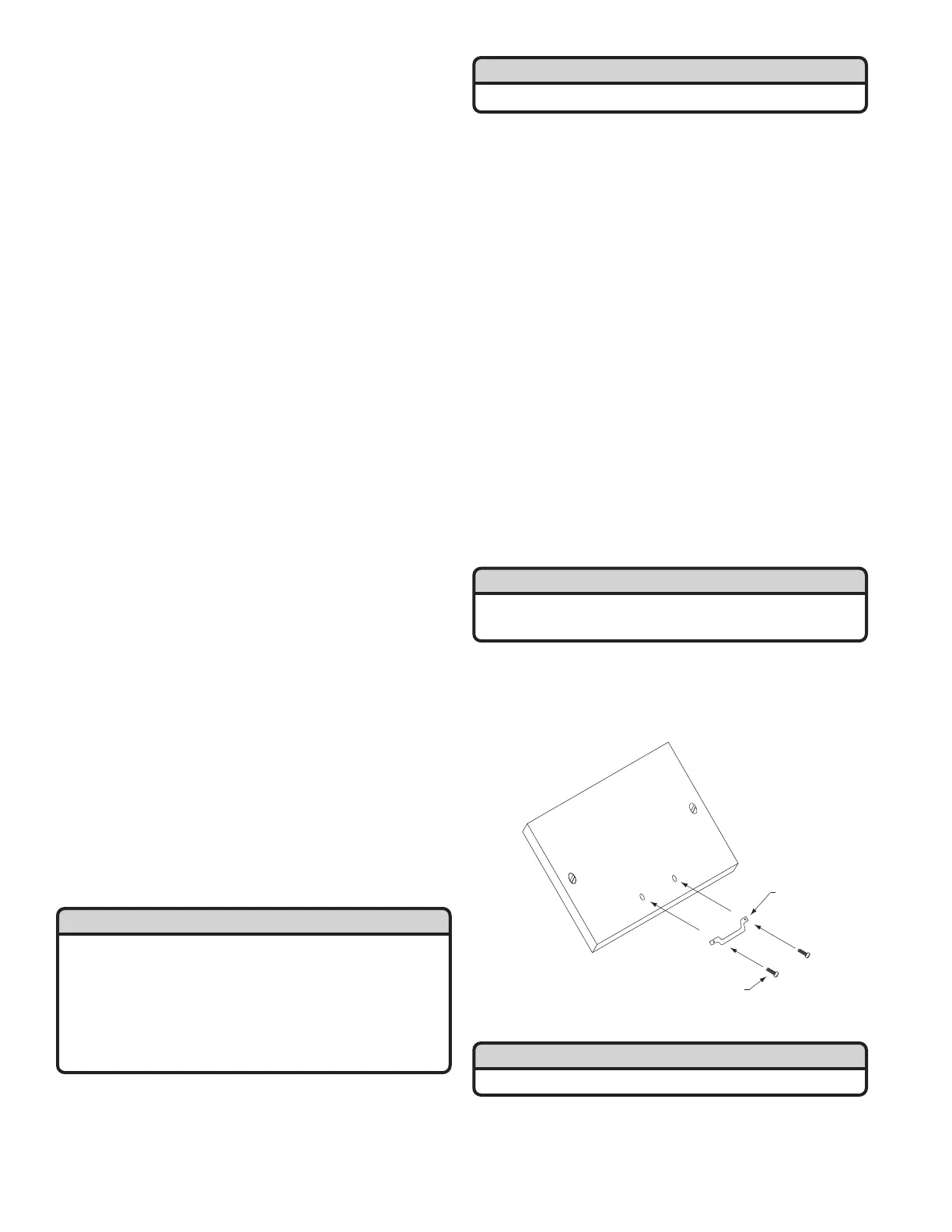
Install Access Panel Handles
Handles for access panels are provided but must be
installed on site. Handles and fasteners are secured on
the top of the unit. Remove from packaging and install
according to drawing below.
Remove All Internal Packaging
Remove access panels and remove all packaging from
the unit. Note that there is packaging for the wheel sup-
port during shipping. Removal of all of this packaging is
critical.
Metal/or
Polyamide
Handle
#10 x 3/4 Screw
Access Panel
CAUTION
All panels must be in place when rigging.
CAUTION
Remove all ERV wheel packaging prior to start up.
IMPORTANT
The hoods for these units are not installed from the fac-
tory and must be installed on-site. They can be installed
prior to rigging the unit or after the unit is installed.
Hoods are shipped on top of the unit. When rigging the
unit, ensure that the hoods are secured and are not
damaged by the spreader bars. See Appendix C for
hood installation and rigging information.
IMPORTANT
Securing door fasteners too tightly has negative effects
on the door gasket and should be avoided.