- 7-
Airflow Balancing
For proper performance the unit must operate with
equal supply and exhaust flow rates. Flow Measuring
Stations (FMS) and magnehelic gauges can be used to
measure and compare supply flow with exhaust flow.
Appendix D shows proper installation of the FMS in the
"exhaust air from space" and "supply air to space" ducts
for measuring exhaust and supply flows respectively.
It is important to locate the FMS in the "warm side"
ductwork as described above to minimize the effect of dif-
ferences in air density, especially when balancing during
extreme cold outside conditions. Air density variations
can effect the FMS by more than 15%.
The FMS should be located downstream from straight
sections of duct and not immediately after fans or
obstructions that will cause turbulent flow. See Appendix
D which illustrates minimum distances from fan, elbows
or transitions for best operation.
Flow control dampers should be installed downstream
from the FMS so flow through the FMS is not disturbed.
Dampers can then be adjusted to equalize flow rates in
the ducts.
Setting Flow Rate
Flow rates should be balanced with units operating on
high speed. A damper must be used to establish the min-
imum duct pressure required so fans do not operate in
overload regions. See Appendix G for airflow perfor-
mance charts. Set the dampers to establish the minimum
duct pressure required. Further adjust the dampers to
reduce flow to the desired, balanced rate.
System Service
Quarterly Maintenance
Quarterly maintenance (every three months) should
include:
Air Filters
The standard medium efficiency filters are disposable
and should be replaced every three months. More fre-
quent replacement may be required under extremely
dirty operating conditions. For filter specifications, see
Appendix F.
Cassette Panels and Interior of Unit
The foil-faced insulation surfaces and cassette panels
should be wiped clean with a soft cloth and mild cleaning
solution.
Annual Maintenance
Annual maintenance should include:
Air Filters
Replace medium efficiency filters.
Interior of Unit
Wash the foil-faced insulation surfaces with a soft cloth
and mild cleaning solution.
Enthalpy Wheel
No cleaning of the enthalpy wheel is required, it is self-
cleaning due to the opposing airflows. If the enthalpy
wheel needs to be cleaned; use low pressure air or a
vacuum. Wash the cassette panels with a soft cloth and
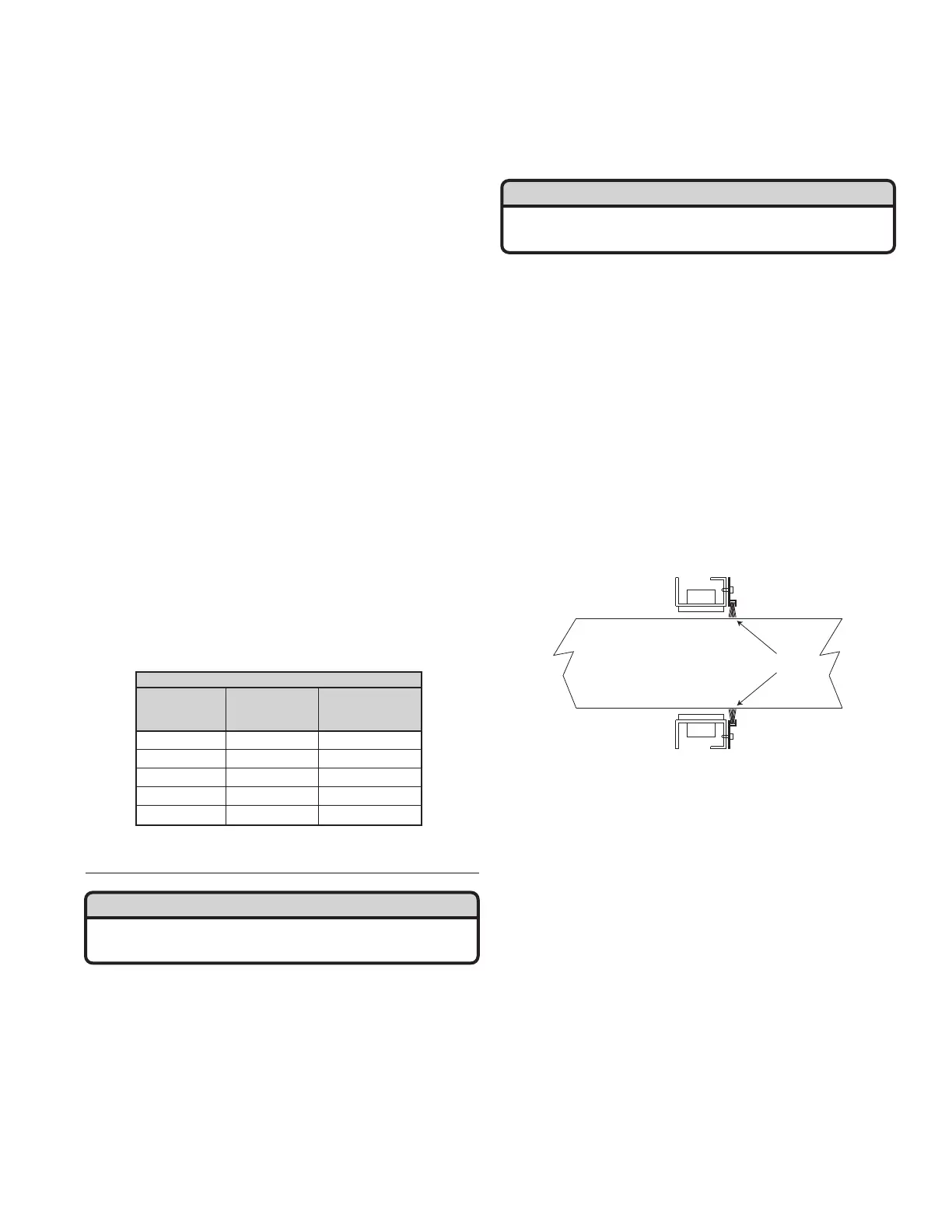
mild cleaning solution. Visually inspect the cassette brush
seals (shown below), perimeter seal and drive belt for
proper operation.
Fans
The blower wheels and fan housing should be checked
for dirt build-up. If they are dirty, it will be necessary to
remove the blower assembly to clean the dust out
through the fan mouth.
System Operation Check
Verification of all control modes should be checked to
ensure proper operation. Refer to Start Up Section.
Testing And Replacement Of The Damper
Actuator
After disconnecting the power from the unit, determine
if the actuator is defective. Disconnect the 24v power
source. Connect the actuator directly to a 24v power
source with an appropriate cable. If the damper operates
correctly, the problem is either in the wiring connections
or main circuit board.
If the actuator does not work, it must be replaced.
Loosen the nuts on the jack shaft clamp, remove the actu-
ator. Tighten the clamp on the damper jack shaft. Test for
proper operation.
ERV500i/e ROTOR
18" Dia. 8" Depth Press. drop
cfm fpm in W. G.
300 417 0.45
400 556 0.60
500 695 0.76
600 834 0.93
700 973 1.10
WARNING
Disconnect the main power switch to the unit before
performing service and maintenance procedures.
WARNING
Disconnect the main power switch to the unit before
performing service and maintenance procedures.