- 20 -
Appendix H Continued
Terminal Control Diagrams
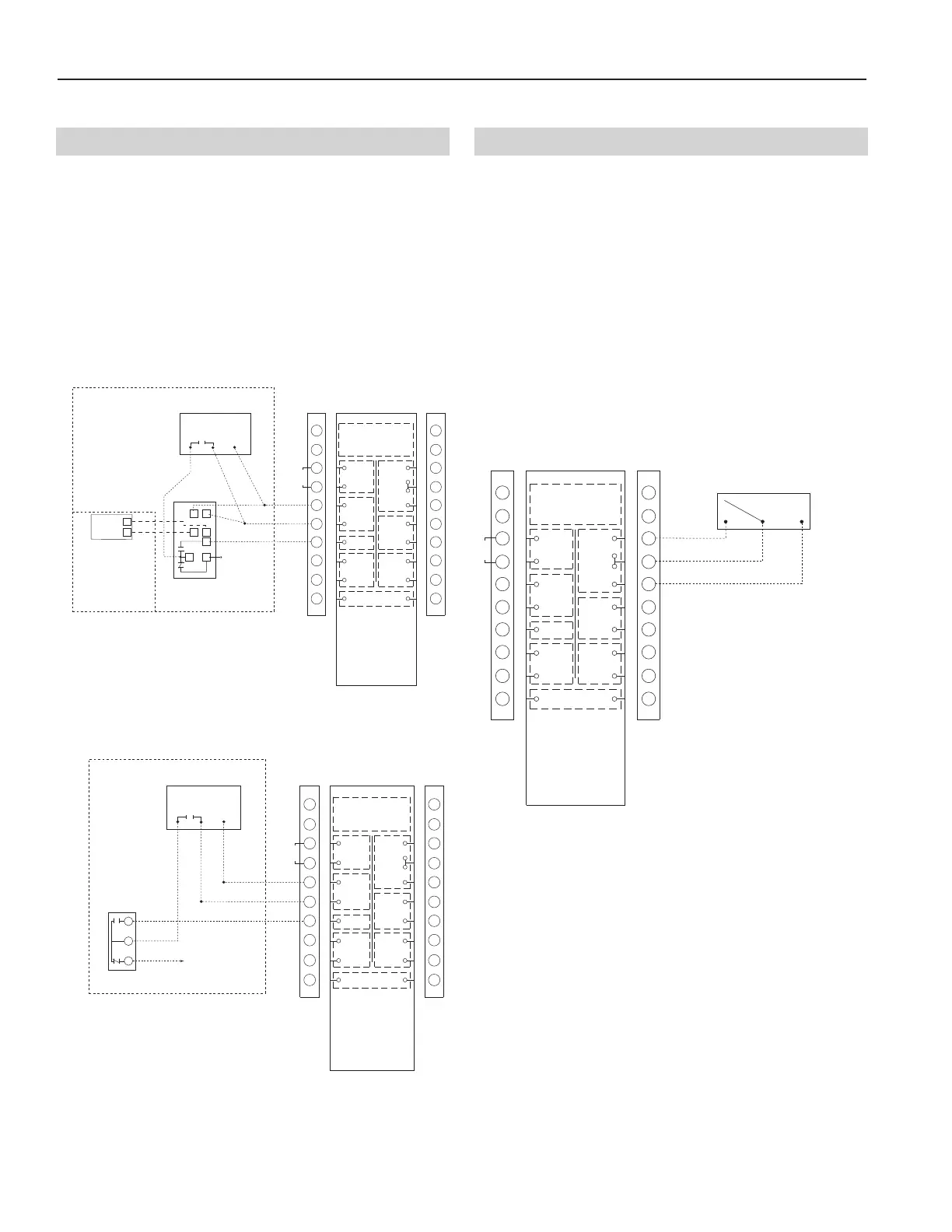
YRC
H705A SETPOINT
ENTHALPY CONTROL
(Mounted in outdoor airstream)
Setpoint PN 1604132 (H705A)
Differential PN 1604131 (H705A and C7400A)
FIELD INSTALLED FREE COOLING CONTROL
WITH SINGLE STAGE COOLING
THERMOSTAT
12
3
+SR
S
+
TR1TR
To A/C Unit
JUMPER
(Field Supplied)
C7400A SENSOR
a
dded for differential
enthalpy control option.
Mounted in return airstream.
CONTROL CONTACTS
CLASS 2 VOLTAGE
W
ALL CONTROL
BLACK
1
2
3
4
5
6
7
8
9
10
1
1
12
13
14
15
16
17
18
19
20
N
OTE:
Connections are all dry contacts
e
xcept wall control, wheel alarm
contacts and 24 VAC power contacts.
U
se of 24 VAC circuit requires
isolating contacts (ex. thermostat)
to prevent interconnection of
C
lass 2 outputs.
R
ED
O
CCUPIED
T
IMER/
S
ENSOR
FIELD WIRED
T
ERMINALS
AB
UNOCC.
R
ECIRC
C
ONTACTS
L
OW
COMMON
HIGH
DIRTY
F
ILTER
INDICATOR
(
1.5A-24 VAC)
(ERV UNITS)
W
HEEL
A
LARM
OPTION
(
24 VAC)
(
ERV UNITS)
E
NTHALPY
(
-) 24 VAC
(40 VA)
(
+) 24 VAC
GREEN
Y
ELLOW
(
RECIRC UNITS)
YRC
T675A SETPOINT CONTROL
(Mounted in outdoor airstream)
Setpoint PN 1604130 (T675A)
FIELD INSTALLED FREE COOLING CONTROL
WITH SINGLE STAGE COOLING
THERMOSTAT
To A/C Unit
JUMPER
(Field Supplied)
CONTROL CONTACTS
CLASS 2 VOLTAGE
WALL CONTROL
BLACK
1
2
3
4
5
6
7
8
9
10
11
12
13
14
15
16
17
18
19
20
NOTE:
Connections are all dry contacts
except wall control, wheel alarm
contacts and 24 VAC power contacts.
Use of 24 VAC circuit requires
isolating contacts (ex. thermostat)
to prevent interconnection of
Class 2 outputs.
RED
OCCUPIED
TIMER/
SENSOR
FIELD WIRED
TERMINALS
AB
UNOCC.
RECIRC
CONTACTS
LOW
COMMON
HIGH
DIRTY
FILTER
INDICATOR
(1.5A-24 VAC)
(ERV UNITS)
WHEEL
ALARM
OPTION
(24 VAC)
(ERV UNITS)
ENTHALPY
(-) 24 VAC
(40 VA)
(+) 24 VAC
GREEN
YELLOW
(RECIRC UNITS)
R
B
W
Remote fan control can be achieved by connecting dry
contact controls to the terminal interface at terminals
labeled: LOW-COM-HIGH (Not all units have two
speeds). Placing a jumper across the 'LOW' and 'COM'
terminals will put the unit in low speed ventilation or plac-
ing a jumper across the 'HIGH' and 'COM' terminals will
put the unit into high speed. DO NOT jumper all three
terminals together. These controls could also be the
following: SPDT switch, dehumidistat, CO
2
sensor, light
sensor, heat sensor, timer, building management system,
etc. The drawing below represents a switch connected to
the unit.
CAUTION: Do not use a wall control and remote fan
switch at the same time. Damage to the
unit may occur.
REMOTE FAN SWITCH
LOW HIGH
NOTE:
CONTROL CONTACTS
CLASS 2 VOLTAGE
WALL CONTROL
B
LACK
1
2
3
4
5
6
7
8
9
10
11
12
1
3
14
15
16
17
18
19
20
NOTE:
Connections are all dry contacts
except wall control, wheel alarm
contacts and 24 VAC power contacts.
Use of 24 VAC circuit requires
isolating contacts (ex. thermostat)
to prevent interconnection of
C
lass 2 outputs.
RED
O
CCUPIED
TIMER/
SENSOR
FIELD WIRED
TERMINALS
AB
UNOCC.
RECIRC
C
ONTACTS
LOW
C
OMMON
H
IGH
DIRTY
FILTER
INDICATOR
(1.5A-24 VAC)
(ERV UNITS)
WHEEL
ALARM
OPTION
(24 VAC)
(ERV UNITS)
ENTHALPY
(-) 24 VAC
(
40 VA)
(+) 24 VAC
G
REEN
YELLOW
(RECIRC UNITS)
Not all units have two speeds.
Single speed units will be
activated with either LOW-COM
or HIGH-COM connection.
JUMPER
H-3: Enthalpy Control H-4: Remote Fan Control
Setpoint/Differential Enthalpy Control
Thermostat (Drybulb) Control
Energy Recovery Ventilators (ERVs) can be controlled
by an enthalpy controller that switches between free cool-
ing and A/C unit cooling. When free cooling is possible,
the ERV will ventilate without energy recovery (the
enthalpy wheel stops) on a call for cooling. The ventilation
rate is not affected. If the unit is not operating, enthalpy
control contact will initiate low speed ventilation. The
enthalpy control must be connected in conjunction with a
cooling thermostat control to prevent free cooling from
initiating in heating seasons as shown below.