- 21 -
Appendix H Continued
Terminal Control Diagrams
ERVs can be equipped with a wheel rotation sensor
option. This option cannot be ordered for a non-defrost
unit. This option cannot be used in conjunction with a dig-
ital wall control and must be ordered with a control board.
With the wheel rotating, the wheel rotation sensor board
activates the relay coil and closes the 'NO' (normally
open) set of contacts across the occupied/timer sensor
contacts (pin 3 and 4), allowing the unit to operate. If the
wheel rotation stops (unless in an enthalpy state, defrost
mode or unoccupied condition), the contacts will be open
and cause the motors to shut down and the dampers
(optional) to close.
NOTE: If the wheel rotation sensor board shuts the unit
down, the only procedure to re-start the unit is to
turn the power off and then back on again.
A set of 24 VAC wheel alarm contacts are available on
the terminals to power a light or indicator. The drawing
below shows the wiring necessary to power the 24 VAC
light or indicator.
CAUTION: The wheel rotation sensor printed circuit
board has 120 VAC wired to two terminals.
Improper wiring or handling of the circuit
board could either damage the board, the
unit or cause personal injury.
LED 1 2 3
NO COM NC 24V COM VENSEN ALA DIS
NO COM NC
24 COM SEN
DEF+ DEF-
CAUTION
120 VAC
DEF+ DEF-
CAUTION
120 VAC
VEN ALA DIS
NO = NORMALLY OPEN
NC = NORMALLY CLOSED
COM = COMMON
24V = 24 VAC
COM = COMMON
SEN = SENSOR
ALA = RELAY ON (24 VAC LIGHT, MAX. 1 AMP)
DIS = ROTATION DETECTOR DISABLE (24 VAC)
VEN = VENTILATION MODE (DISABLE WRS) (24 VAC)
DEF+ = DEFROST MODE (DISABLE WRS) (120 VAC)
DEF- = DEFROST MODE (DISABLE WRS) (120 VAC)
NO NC
RELAY
COM SEN
COM
SENSOR
MAGNET
J1 J2
DELAY
J1 J2
DELAY
LED 1 2 3
J1 & J2 = DETECTION DELAY
J1 J2 DELAY
1 min.
X 2 min.
X 4 min.
X X 8 min.
*default
1 = RELAY ON (RED)
2 = POWER ON (GREEN)
3 = SENSOR DETECTION INDICATOR (YELLOW)
*
24 VAC LIGHT or INDICATOR
(Supplied by others)
WRS BOARD RELAY
'N/C' CONTACTS
(Normally closed -
opens on wheel failure)
CONTROL CONTACTS
CLASS 2 VOLTAGE
WALL CONTROL
BLACK
1
2
3
4
5
6
7
8
9
10
11
12
13
14
15
16
17
18
19
20
NOTE:
Connections are all dry contacts
except wall control, wheel alarm
contacts and 24 VAC power contacts.
Use of 24 VAC circuit requires
isolating contacts (ex. thermostat)
to prevent interconnection of
Class 2 outputs.
RED
OCCUPIED
TIMER/
SENSOR
FIELD WIRED
TERMINALS
AB
UNOCC.
RECIRC
CONTACTS
LOW
COMMON
HIGH
DIRTY
FILTER
INDICATOR
(1.5A-24 VAC)
(ERV UNITS)
WHEEL
ALARM
OPTION
(24 VAC)
(ERV UNITS)
ENTHALPY
(-) 24 VAC
(40 VA)
(+) 24 VAC
GREEN
YELLOW
(RECIRC UNITS)
H-6: Wheel Rotation Sensor
Wheel Rotation Sensor Board
Wheel Rotation Alarm
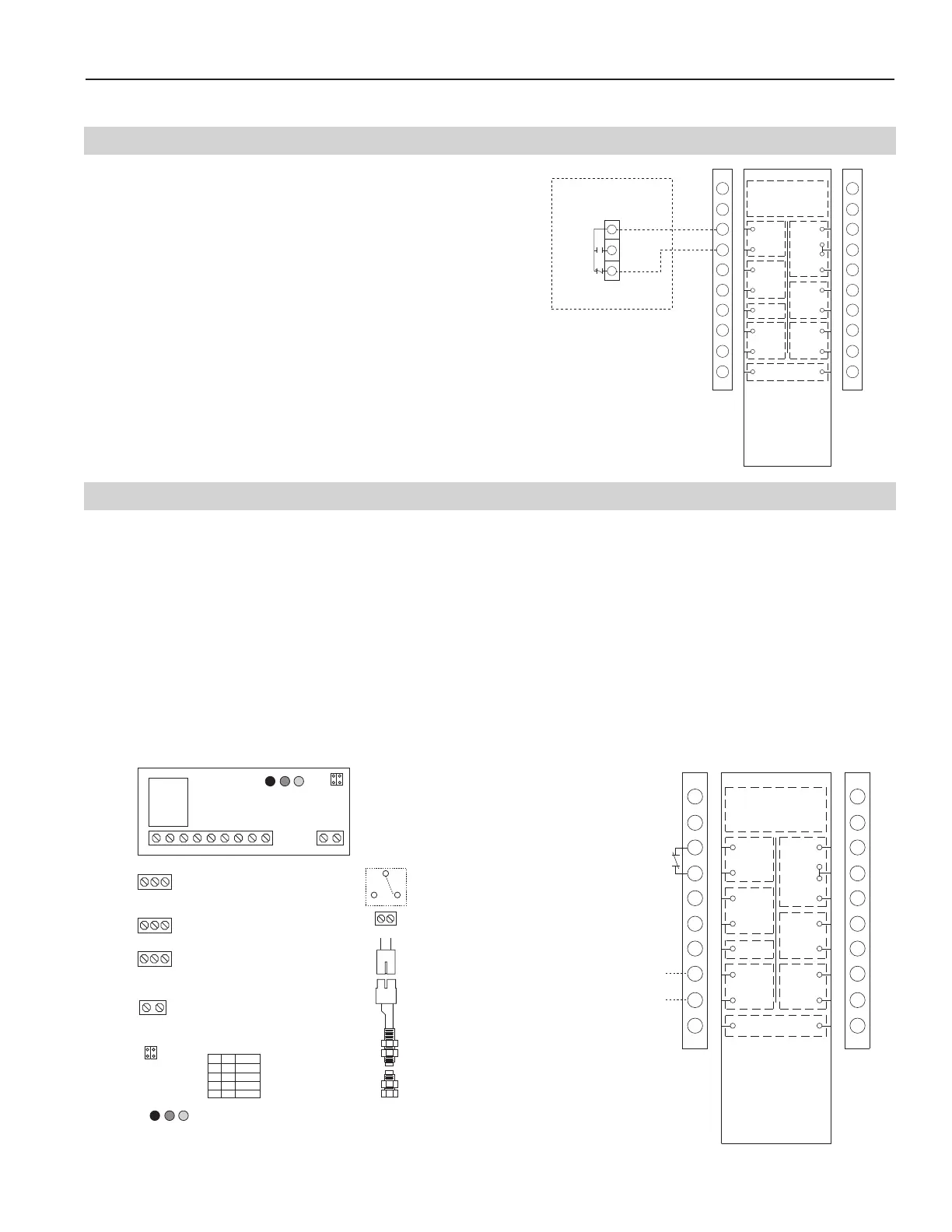
The fans of the ERV can be controlled using a setpoint
low temperature controller. If the supply air discharge tem-
perature falls below the setpoint on the low temperature
controller, the contacts between R-W break, therefore, de-
energizing the fans and closing the outside air damper.
NOTE: An Xtra wall control cannot be used with a low
temperature control.
NOTE: The remote bulb sensor must be placed down-
stream of the supply air fan discharge.
H-5: Low Temperature Control
T675A SETPOINT CONTROL
Field Installed
Low Temperature Unit Control
R
B
W
NOTE:
1
) R - W breaks on temperature fall
2
) Sensing bulb is placed in supply air
s
tream after the energy exchanger
CONTROL CONTACTS
CLASS 2 VOLTAGE
WALL CONTROL
BLACK
1
2
3
4
5
6
7
8
9
1
0
1
1
12
1
3
1
4
1
5
1
6
1
7
1
8
1
9
2
0
NOTE:
Connections are all dry contacts
except wall control, wheel alarm
c
ontacts and 24 VAC power contacts.
Use of 24 VAC circuit requires
isolating contacts (ex. thermostat)
to prevent interconnection of
C
lass 2 outputs.
RED
O
CCUPIED
TIMER/
SENSOR
FIELD WIRED
T
ERMINALS
A
B
UNOCC.
R
ECIRC
CONTACTS
L
OW
COMMON
HIGH
DIRTY
F
ILTER
I
NDICATOR
(1.5A-24 VAC)
(ERV UNITS)
WHEEL
ALARM
OPTION
(
24 VAC)
(
ERV UNITS)
ENTHALPY
(
-) 24 VAC
(40 VA)
(
+) 24 VAC
GREEN
YELLOW
(
RECIRC UNITS)