- 22 -
Appendix H Continued
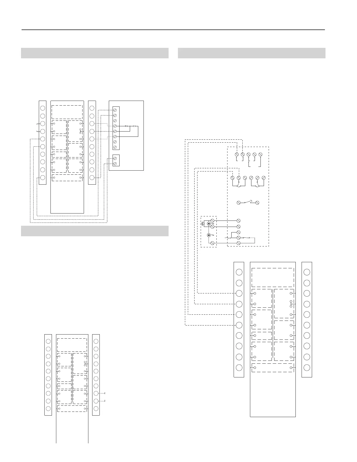
Terminal Control Diagrams
AVAILABLE POWER INPUTS
1 2 12 13 14
2
4V
120
V
AC
220/240
V
AC
ALARM AUXILIARY CONTACTS
FOR FAN SHUTDOWN, ETC.
15 16 17 18 19 20
ALARM AUXILIARY CONTACTS SHOWN IN
STANDBY. CONTACTS TRANSFER DURING
ALARM AS INDICATED BY THE ARROWS.
N.C. C. N.O.
N.O.
C.
N.C.
8
9
N.O.
ALARM INITIATION CONTACTS
TROUBLE CONTACTS CLOSED IN ALARM AND
STANDBY. CONTACTS OPEN WHILE DETECTOR
HEAD OR POWER IS REMOVED, AND DURING
RESET. OPEN CONTACTS SIGNAL TROUBLE
CONDITION TO PANEL.
2 ALARM 5
1 COMMON 6
7
10
3 POWER 11
(+) ALARM SIGNAL
(D) AUX POWER
(+) AUX POWER
TROUBLE
CONTACTS
FIELD
INSTALLED
JUMPER
GRN.
RED
POWER INPUTS ACCEPT
24 VDC, 24 VAC 50-60 HZ,
120 VAC 50-60 HZ, OR
220/240 VAC 50-60 HZ.
CONNECT POWER SOURCE
T
O APPROPRIATE TERMINALS
O
F EACH DETECTOR.
ALARM AUXILIARY CONTACT RATINGS
10A @ 30 VDC
1
0A @ 250 VAC (0.75 POWER FACTOR)
240VA @ 240 VAC (0.4 POWER FACTOR)
1/8 HP @ 120 VAC
1/4 HP @ 240 VAC
500mA MINIMUM @ 24 VDC
NOT INTENDED FOR CONNECTION
TO CONTROL PANELS.
A
LARM INITIATION CONTACT RATING
2
.0A @ 30 VAC/DC (0.6 POWER FACTOR)
TROUBLE CONTACT RATING
0.3A @ 32 VAC/DC
TROUBLE CONTACTS CLOSED IN STANDBY
AND ALARM. CONTACTS OPEN WHILE
DETECTOR HEAD OR POWER IS REMOVED,
AND DURING RESET. OPEN CONTACTS
E
XTINGUISH OPTIONAL APA451 GREEN
P
OWER LED TO INDICATE TROUBLE
CONDITION.
CONTROL CONTACTS
CLASS 2 VOLTAGE
WALL CONTROL
BLACK
1
2
3
4
5
6
7
8
9
10
11
12
13
14
15
16
17
18
19
20
NOTE:
Connections are all dry contacts
except wall control, wheel alarm
contacts and 24 VAC power contacts.
Use of 24 VAC circuit requires
isolating contacts (ex. thermostat)
to prevent interconnection of
Class 2 outputs.
RED
OCCUPIED
TIMER/
SENSOR
FIELD WIRED
TERMINALS
AB
UNOCC.
RECIRC
CONTACTS
LOW
COMMON
HIGH
DIRTY
FILTER
INDICATOR
(1.5A-24 VAC)
(ERV UNITS)
WHEEL
ALARM
OPTION
(24 VAC)
(ERV UNITS)
ENTHALPY
(-) 24 VAC
(40 VA)
(+) 24 VAC
GREEN
YELLOW
(RECIRC UNITS)
Locate in a normally occupied area of premises.
Recommended for compliance to NFPA-90A and IMC
code 606.
ERVs can be equipped with a duct mount smoke detec-
tor which will monitor the air when passing through the
duct system into the ERV. When sufficient smoke is
detected, an alarm condition is activated. By connecting
the occupied timer/sensor contacts to the N/C alarm aux-
iliary contacts on the duct sensor, an alarm condition will
open the auxiliary contact and stop operation of the ERV.
H-9: Smoke Detector
ERVs can be controlled by a CO
2
controller that can be
connected to fan control LOW-COM-HIGH (Not all units
have two speeds). As the CO
2
levels exceed acceptable
limits, the dry contact across HIGH-COM is closed, rais-
ing high speed fan ventilation.
H-7: CO
2
Ventilation Control
FACTORY MOUNTED
JUMPER
CO
2
SENSOR
AC INPUT
AC GROUND
N
C NO
CONTROL CONTACTS
C
LASS 2 VOLTAGE
W
ALL CONTROL
B
LACK
1
2
3
4
5
6
7
8
9
10
11
8
12
13
14
1
5
16
17
18
1
9
20
N
OTE:
C
onnections are all dry contacts
except wall control, wheel alarm
contacts and 24 VAC power contacts.
U
se of 24 VAC circuit requires
i
solating contacts (ex. thermostat)
t
o prevent interconnection of
C
lass 2 outputs.
NOTE 1: Terminal 5 on CO
2
Sensor
used only with 2 speed units.
NOTE 2: Terminal 7 and 8 on CO
2
Sensor used only with blower VFDs.
NORMAL OPERATION - LOW SPEED
C
O
2
L
EVELS EXCEED SETPOINT - HIGH SPEED
R
ED
O
CCUPIED
T
IMER/
SENSOR
FIELD WIRED
T
ERMINALS
AB
U
NOCC.
R
ECIRC
C
ONTACTS
L
OW
COMMON
HIGH
D
IRTY
F
ILTER
I
NDICATOR
(
1.5A-24 VAC)
(ERV UNITS)
WHEEL
A
LARM
O
PTION
(
24 VAC)
(
ERV UNITS)
E
NTHALPY
(-) 24 VAC
(
40 VA)
(
+) 24 VAC
G
REEN
Y
ELLOW
(RECIRC UNITS)
7
6
5
3
2
1
2
1
4
H-8: Unoccupied Recirc Contacts (ERV500i ONLY)
CONTROL CONTACTS
CLASS 2 VOLTAGE
WALL CONTROL
BLACK
1
2
3
4
5
6
7
8
9
10
11
12
13
14
15
16
17
18
19
20
NOTE:
Connections are all dry contacts
except wall control, wheel alarm
contacts and 24 VAC power contacts.
Use of 24 VAC circuit requires
isolating contacts (ex. thermostat)
to prevent interconnection of
Class 2 outputs.
RED
OCCUPIED
TIMER/
SENSOR
FIELD WIRED
TERMINALS
AB
UNOCC.
RECIRC
CONTACTS
LOW
COMMON
HIGH
DIRTY
FILTER
INDICATOR
(1.5A-24 VAC)
(ERV UNITS)
WHEEL
ALARM
OPTION
(24 VAC)
(ERV UNITS)
ENTHALPY
(-) 24 VAC
(40 VA)
(+) 24 VAC
GREEN
YELLOW
(RECIRC UNITS)
NOTE:
Unoccupied Recirculation is available on
units with Recirculation Defrost Option only.
24 VAC
Required
On recirc defrost units, an unoccupied recirc control
can be achieved by connection to the terminal interface
shown below. These terminals require a 24 VAC signal
which could be provided by a timer, thermostat or other.
Closure of these terminals will cause the unit to go into a
'recirc mode' where the supply fan runs on high speed
and the exhaust fan stops.
NOTE: Although these contacts are intended for use
during unoccupied periods, they are still active
during an occupied condition. Therefore, the 24
VAC signal should be applied such that it is dis-
abled during occupied periods, preventing the unit
from going into a recirc condition unnecessarily.