5. CONTROLS (CONT’D)
14
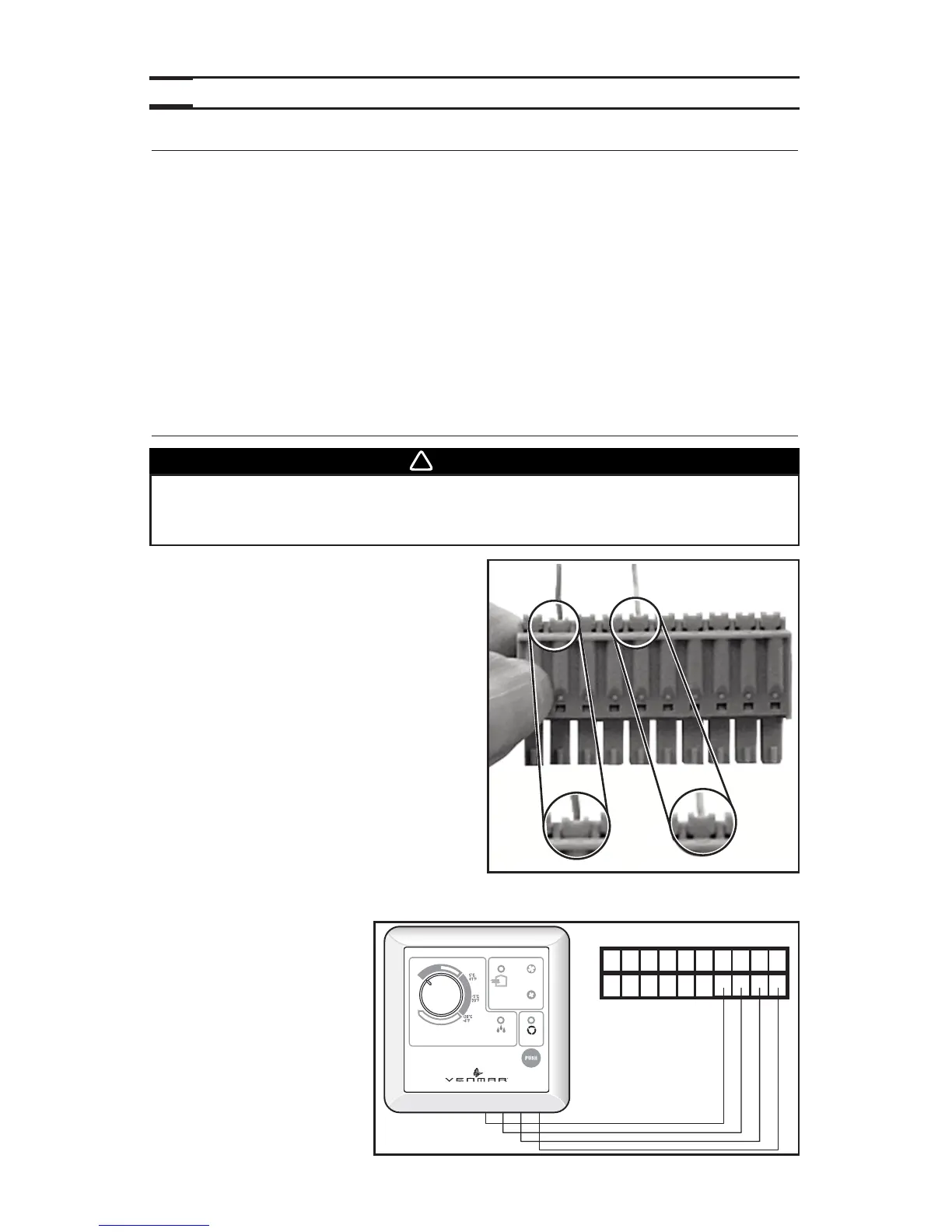
5.2 CONTROLS CONNECTION TO THE UNIT
Use the terminal connector included in the
installation kit to perform the electrical
connection for control. Check if all wires are
correctly inserted in their corresponding holes
in the terminal block. (A wire is correctly
inserted when its orange receptacle is lower
than another one without wire. On picture
beside, wire A is correctly inserted, but not
wire B.)
5.2.1 BREEZE MAIN CONTROL (PRO250 ONLY)
NO C NC I OC OL Y R G B
VE0180
C
O
M
F
O
R
T
Z
O
N
E
V
I
T
E
S
S
E
M
A
X
.
P
E
E
D
4
0
2
6
0
V
-
1
0
3
/
2
0
0
7
MIN.
AUTO
ÉCHANGE
AIR
EXCHANGE
RE-CIRC
EXCÈS D’HUMIDITÉ
EXCESS HUMIDITY
É
T
É
/
S
U
M
M
E
R
WARNING
Always disconnect the unit before making any connections. Failure in
disconnecting power could result in electrical shock or damage of the
control or electronic module inside the unit.
BOOT SEQUENCE
The unit boot sequence is similar to a personal computer boot sequence. Each times the unit
is plugged after being unplugged, or after a power failure, the unit will perform a30-second
booting sequence before starting to operate. During the booting sequence, the integrated
control LED will light GREEN or AMBER for 5 seconds, and then will shut off for 2 seconds.
After that, the LED will light RED for the rest of the booting sequence. During this RED light
phase, the unit is checking and resetting the motorized damper position. Once the motorized
damper position completely set, the RED light turns off and the booting sequence is done.
NOTE: No command will be taken until the unit is fully booted.
5.1 INTEGRATED CONTROL (CONT’D)
If a problem occurs during the unit operation, its integrated control LED (2) will blink. The
color of the blinking light depends on the type of error detected. Refer to Section 8
Troubleshooting
on page 20 for further details.
A B