27
Rev. 01.01
COMMISSIONING
5. COMMISSIONING
READ CAREFULLY!
Select the type of sensor connected to the unit.
Select NO if no sensor is connected. If the correct
parameters are not set, the unit may give an error
message and not operate properly.
MENU 09 - TEMPERATURE PROBE
Choose the sensor to be used for maintaining the
set point temperature
Temperature probe
Blowing
Suction
Surroundings
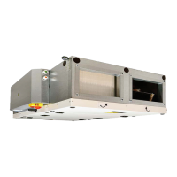
The calibration takes several minutes. Do not dis-
connect the unit, wait until it's completed. During
the calibration the unit determines the maximum
pressure loss, when the fan runs at full rate.
READCAREFULLY!Theunitwillnotwork
properly if, during calibration, the distri-
butionnetworkisnotcomplete,theaps
or valves are not closed, etc.
1000 cfm 0.12 iwg
MENU 05 - FILTER CALIBRATION
The calibration has to be carried out during the
rst commissioning and when switching to a new
type of lter.
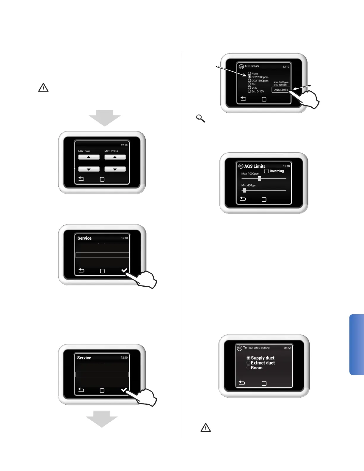
MENU 08 - AQS SENSOR
Select Air
Quality
Sensor
Type
Set Sensor
Reading
Thresholds
04 - Fan Calibration
05 - Filter Calibration
08 - AQS Sensor
09 - Temp Sensor
10 - Supply Duct Limit
02 - HW Setting
04 - Fan Calibration
05 - Filter Calibration
08 - AQS Sensor
09 - Temp Sensor
Select the minimum and maximum threshold val-
ues for Air Quality Sensor.
The HRV will run at the minimum ow rate when
the sensor reading is at or below the minimum
threshold. Airow is increased in a linear fashion
as the reading increases until maximum system
ow rate is reached at the max threshold.
Breathing in DCV
When enabled, the ow rate is set to 0 CFM
until the sensor reading is above the minimum
threshold. To obtain an accurate reading of air
quality, the unit will periodically run at an in-
creased ow rate for a short period of time to
circulate air through the system.
Note: Enabling room temperature re-
quires an additional accessory sensor