OUTBOARD ENGINE KIT INSTALLATION
B001167
OUTBOARD ENGINE KIT
INSTALLATION
WARNING
Before beginning, disconnect the negative terminal on the battery, otherwise you risk a short circuit.
If the vehicle is supplied by auxiliary batteries, you must also disconnect the negative terminals on
these batteries! Short circuits can cause fires, battery explosions and damages to other electronic
systems. Please note that when you disconnect the battery, all volatile electronic memories lose their
input values and must be reprogrammed.
• The IBS must be mounted and handled in an ESD protected area
• The IBS may not be contaminated with foreign particles (e.g., oil, silicon, grease, coolant, etc.)
• The IBS may not be damaged
• The pole clamp may only be torqued to the battery pole
PACKAGING CONTENT
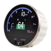
Intelligent Battery Sensor
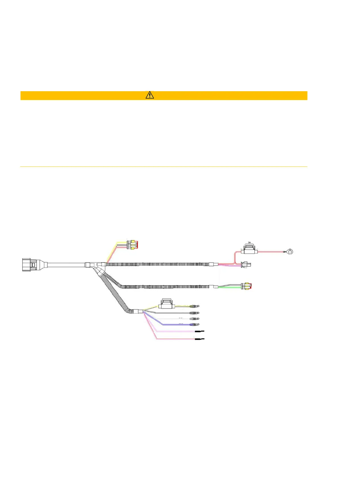
HARNESS
Day/Night switch (red/white)
Ring Connector for battery plus (with fuse)
(blue)
A
B
I
G
H
J
K