ELECTRICAL SCHEMATICS
B001167
ELECTRICAL SCHEMATICS
WARNING
• Refer to the safety rules described in the electrical connections section of the safety information
chapter of this document!
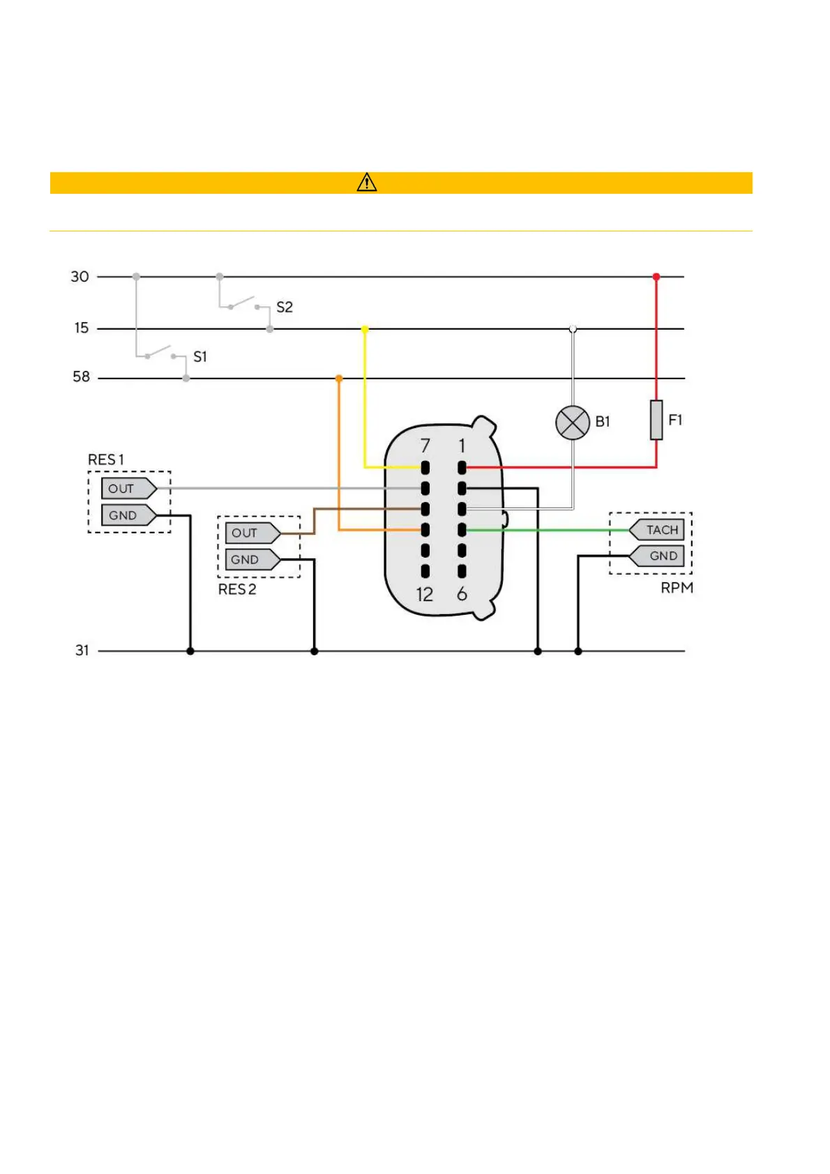
Designations in the circuit diagram:
30 - KL.30 – Battery Power 12V
15 - KL. 15 - Ignition positive
31 - KL. 31 - Ground
58 - KL.58 – Illumination positive
S1 - Day/Night mode switch (not included)
S2 - Ignition key
F1 - 3A fuse (not included)
B1 - External beeper (not included)
RES 1 - Resistive analogue input 1
RES 2 - Resistive analogue input 2
RPM - Frequency Analog Input