SETUP
Examining Unit Features
16 V200C AND V400C INSTALLATION GUIDE
Connection Ports
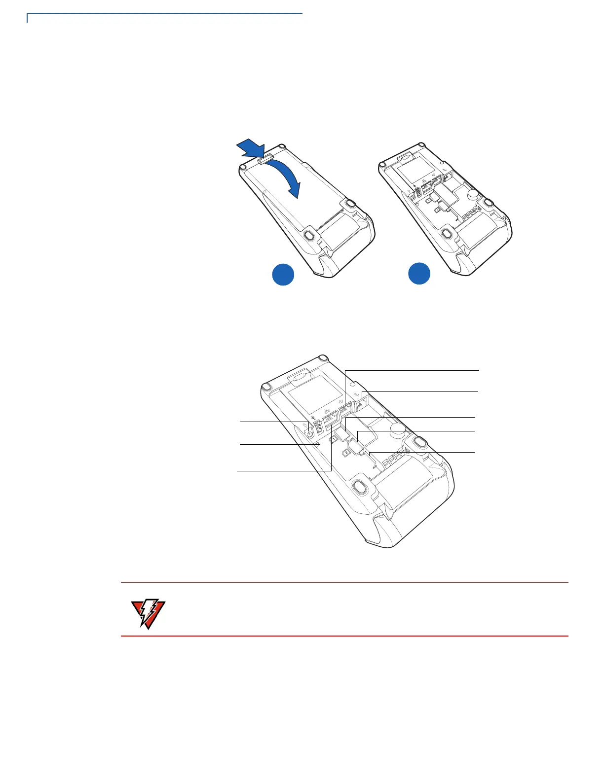
Turn the terminal upside down and remove the rear cover to view the connection
ports. Notice that the ports are recessed. Different ports provide connections to
communications lines, optional peripheral devices, and the power supply.
Figure 2 shows how to open the rear cover of the V200c and V400c device.
Figure 2 Opening the Rear Cover
Figure 3 shows the power, communications and connection ports for V200c and
V400c devices.
Figure 3 Power and Connection Ports
POWER PORT
HOST USB
PORT
ETH PORT
MULTI-
TELCO PORT
SAM 1 SLOT
SAM 2 SLOT
MICRO SD CARD
SLOT
(V200C PLUS AND
COMMUNICATION
PORT (USB/RS-232)
V400C PLUS ONLY)
Do not connect the terminal to the power supply until all the peripherals are
connected.
 Loading...