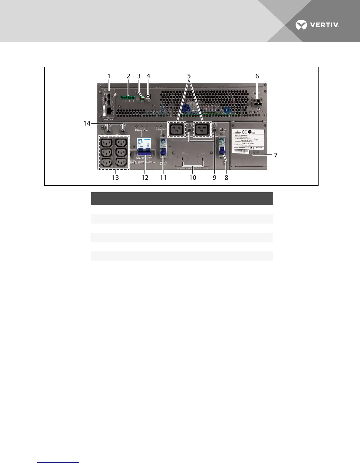
Figure 2.2 Rear panel—5000VA and 6000VA
NO. DESCRIPTION NO. DESCRIPTION
1 Liebert IntelliSlot Unity-DP card 8 Input circuit breaker
2 Terminal-block communication 9 Output circuit breakers
3 REPO 10 Knockouts for hard-wired power input and output
4 USB port 11 Output circuit breaker
5 C19 output-power receptacles 12 Maintenance bypass breaker
6 External battery connector 13 C13 output receptacles
7 IT Power System access cover 14 Output circuit breakers
NOTE: Hard-wired and hard-wired/receptacle boxes that include a manual bypass switch permit AC
power to continue to flow from the utility input to the load while the box is removed from the UPS. For
details, refer to Connecting Input/Output Power on page 25.
Vertiv | Liebert GXT4 Installer/User Guide | 13