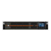
INDICATOR COLOR DESCRIPTION
Inverter Green On when the inverter is supplying power
Bypass Amber On when the load is supplied by the mains through automatic/manual bypass
Battery Amber On when the load is supplied by the battery
Fault Red On when an error has occurred within the UPS
ECO Mode Green On when the UPS is in ECO Mode
Table 4.1 LED indicators
4.2 Control Buttons
The control buttons are described in the following table.
BUTTON DESCRIPTION
ESC Pressing this button returns to the previous menu or aborts any change in the input data field before confirming.
Up
Pressing this button can move the cursor up or increase the value displayed in the input data field. When a menu is displayed on several
screens, pressing the button can scroll up.
Down
Pressing this button can move the cursor down or decrease the value displayed in the input data field. When a menu is displayed on
several screens, pressing the button can scroll down.
Enter Pressing this button can enter the next level menu or confirm the parameter setting value.
Table 4.2 Control buttons
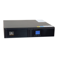
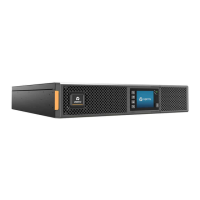
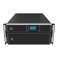
4.3 LCD
The LCD panel shows the UPS status and enables changes to the UPS settings by assisting in navigating
through the GXT4 menu (see Menu Structure on page 33).
Vertiv | Liebert GXT4 Installer/User Guide | 32