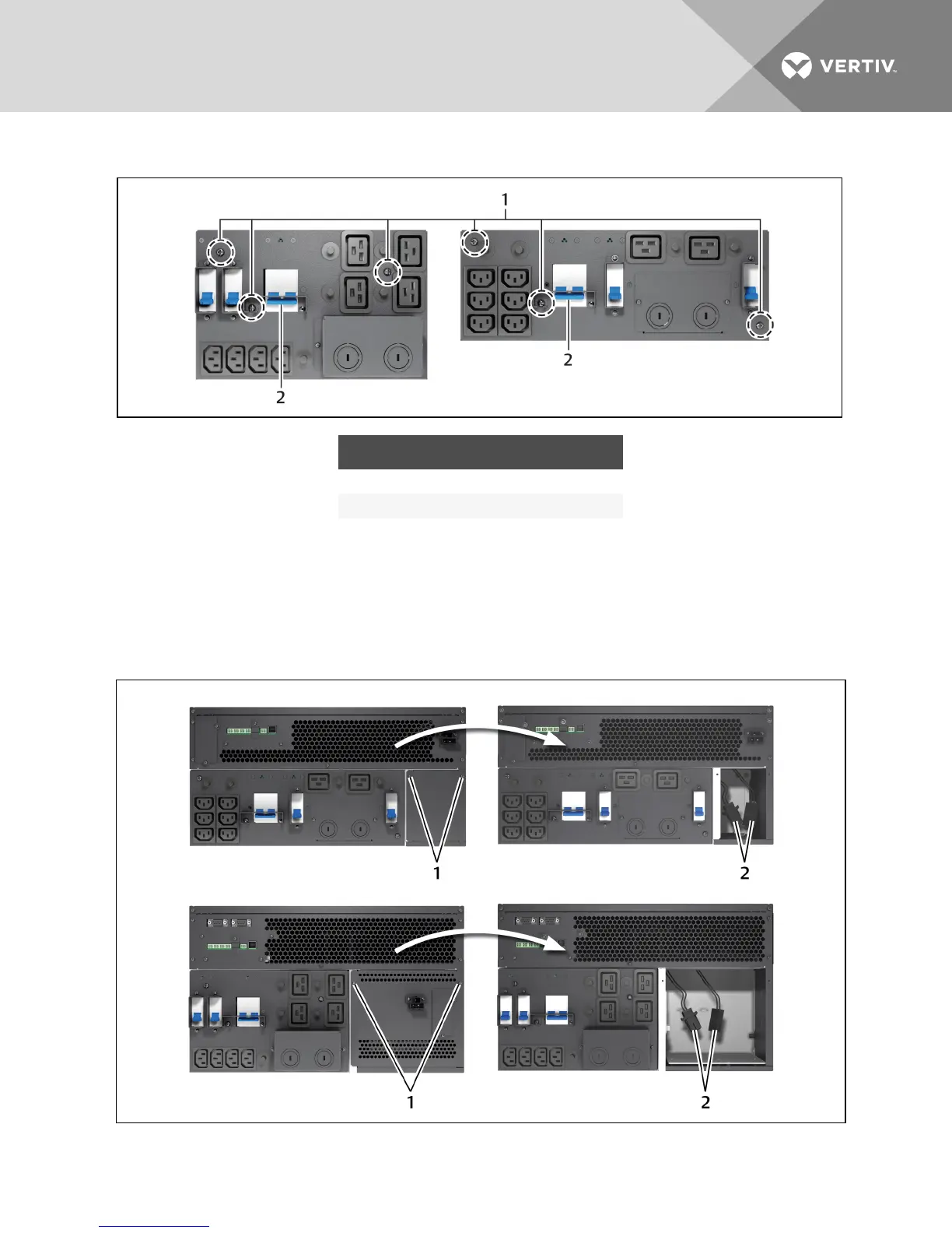
Figure 3.6 Power distribution box removal
NO. DESCRIPTION
1 Captive screws to loosen.
2 Maintenance bypass breaker
3.7 Configuring an IT Power System
1. Remove screws on the IT Power System Access Cover as shown in the figure.
2. Disconnect the connectors as shown in the figure.
3. Install the IT Power System Access Cover and screws.
Figure 3.7 Remove cover from IT Power System Connectors compartment
Vertiv | Liebert GXT4 Installer/User Guide | 28