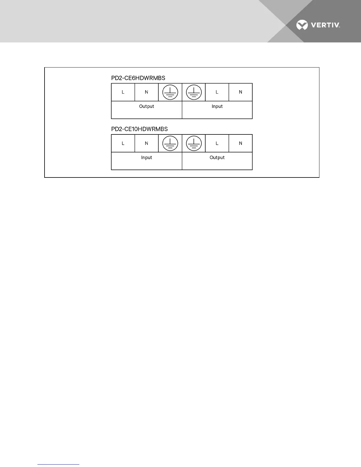
Figure 3.5 Terminal block connections
1. We recommend installing a breaker upstream of unit.
2. The installer must provide circuit breaker protection according to local codes. The mains
disconnect should be within sight of the UPS or have appropriate an appropriate lock-out.
Maintain service space around the UPS or use flexible conduit.
3. The installer must provide output distribution panels, circuit breaker protection or emergency
disconnects according to local codes. Output circuits must not share a common conduit with
any other wiring.
3.6.3 Removing the Power Distribution Box
1. Manually transfer the connected equipment to the internal bypass.
a. From the main menu select CONTROL, then press Enter.
b. Select T UR N O N & O FF and press Enter.
c. Select T UR N O N UPS BYPAS S and press Enter.
The UPS transfers the connected loads to the internal bypass. (For help, refer to
Performing Manual Bypass on page 42.)
d. Loosen the captive screw over the maintenance bypass breaker (see the following figure
for the breaker’s location).
e. Turn the maintenance bypass breaker On.
NOTICE
The load is unprotected from disturbances in the power supply while the UPS is on bypass.
2. Turn the output and input breakers Off.
3. Loosen other captive screws until the power distribution box releases.
4. Remove the power distribution box from the UPS and set it aside.
5. On the rear of the panel, loosen the screws of the protective cover for the connectors, slide it
over the connectors, and tighten the screws.
Vertiv | Liebert GXT4 Installer/User Guide | 27