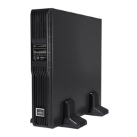
Figure 5.10 Terminal block connections
NOTE: Emerson recommends installing a UL489-approved breaker upstream of unit.
NOTE: The installer must provide circuit breaker protection according to local codes. The utility disconnect should be
within sight of the UPS or have appropriate an appropriate lock-out. Maintain service space around the UPS or use
flexible conduit.
NOTE: The installer must provide output distribution panels, circuit breaker protection or emergency disconnects
according to local codes. Output circuits must not share a common conduit with any other wiring.
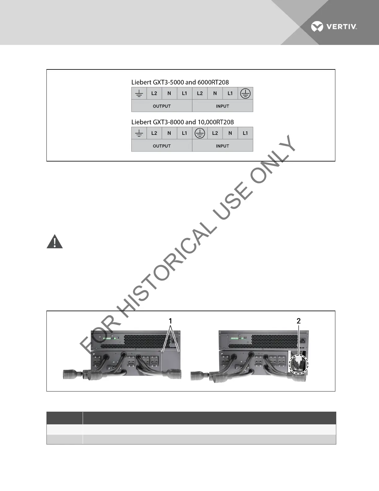
5.4 IT Power System Configuration—Liebert GXT3-6000RTL630 Only
WARNING! Risk of electric shock. Can cause injury or death. Disconnect all local and remote electric power
supplies before working within. Ensure that the Liebert GXT3 is shut down and power has been
disconnected before beginning any work on or in the unit.
1. Remove screws on the IT Power System Access Cover as shown in Figure 5.11 below.
2. Disconnect the connectors as shown in figure.
3. Reinstall IT Power System Access Cover and screws.
Figure 5.11 Remove cover from IT Power System Connectors compartment
ITEM DESCRIPTION
1 Remove Screws
2 IT Power System Connectors
Table 5.10 Compartment Descriptions
Vertiv | Liebert® GXT3 ™ Installer/User Guide | 33
 Loading...