8
English
Liebert HPM --- A/W/F/D/H
4.1.2 --- Pipe diameter
The diameters of the connecting pipes between the condi-
tioner and the condensing unit listed in Tab. c must be re-
spected, otherwise the guarantee becomes invalid.
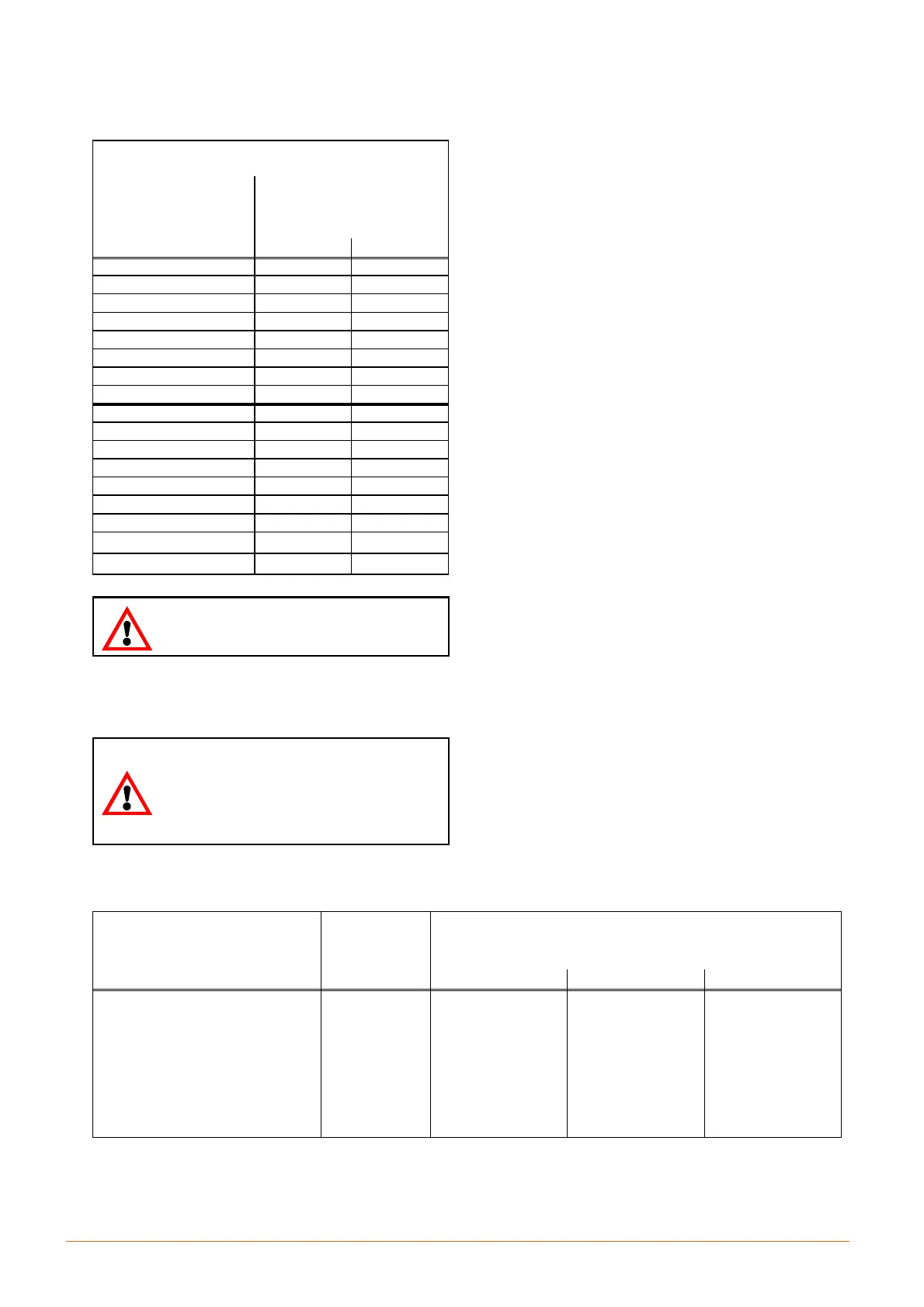
Ta b . c --- Pipe diameters (room unit --- remote condenser)
STANDARD PIPE DIAMETERS
(Valid for equivalent lengths up to 50 m)
MOD.
copper tube
external diametre x thickness
[mm]
R410A
Gas Liquid
S0F 10 X 1 10 X 1
S0H 12 X 1 12 X 1
S1A 12 X 1 12 X 1
S1D 14 X 1 14 X 1
S1E 14 X 1 14 X 1
S1G 16 X 1 16 X 1
S2E 18 X 1 16 X 1
S2G 22 X 1.5 18 X 1
M2H---M3A 22 X 1.5 18 X 1
M3F 16 X 1 16 X 1
M3G 22 X 1.5 18 X 1
M4E---M5B 22 X 1.5 18 X 1
M4H 18 X 1 16 X 1
M5C---M5D 22 X 1.5 18 X 1
M7L 22 X 1.5 18 X 1
L8F
28 X 1.5 22 X 1.5
L9H
28 X 1.5 22 X 1.5
Whenthepipesaremorethan50mlong,
contact Technical Support Department
4.1.3 --- Installing pipelines
THE FOLLOWING OPERATIONS MUST BE CARRIED OUT
BY AN EXPERIENCED REFRIGERATION TECHNICIAN.
The discharge operation of the room unit
pressurized with helium (at 1 bar) and the
de ---welding of the b ottoms from the
connections must be carried out as last
operations, immediately followed by the
connection and emptying of the whole
system.
1) Lay the piping, taking note of the follo wing:
S Welding:
S All joints must be braze---welded.
S Avoid butt welds by using sleeves or enlarging
one of the pipes using a pipe opener.
S Use silver---based solders and the correct appar-
atus.
S Guarantee a corre ct weld as a refrigerant leak, or
a faulty weld which leads to a leak later on, can
seriously damage the air conditioner.
S Always use large---radius curves (bending radius at
least equal to pipe diameter). Bend the pipes as fol-
lows:
S soft copper: by hand or bending device.
S hard copper: use preformed curves. Do not over-
heat the pipes when welding so as to minimize
oxidation.
2) Connect the pipes to the condenser:
S Condensers with butt---welded pipe connec tions:
cut the pipe, enlarge it and weld it to the pipeline.
S Condense rs with threaded tap connections: flange
the pipes and connec t.
RESPECT THE DIRECTION OF REFRIGERANT
FLOW (SEE LABELS ON REFRIGERANT CON-
NECTIONS).
3) Wash out the pipelines as follows:
a) Plug up the free ends of the pipes.
b) Connect a helium or nitrogen cylinder, fitted with a re-
ducer (max. pressure 10 bar), to the ¼” SAE
Schrader valve of the condenser.
c) Pressurize the pipes with helium or nitrogen.
d) Unplug the pipes instantaneously.
e) Repeat a) --- d) several times.
THIS OPERATION IS ESPECIALLY IMPORTANT WHEN
HARD COPPER PIPING IS USED.
4) Open all the room unit shut---off valve.
5) Discharge the room unit pressurized with helium (at 1
bar) opening the charge valves so that all the branches
of the circuit are discharged (e.g. on the receiver, on the
low pressure side and on the compressor delivery).
6) De---weld the bottoms from the
connections of the room
unit.
7) Fix (weld) the pipes to the connections on the air condi-
tioner.
8) Connect the refrigerant safety valve to the outdoor with
a copper pipe sized in order to satisfy the requirements
of EN13136 (i.e. till 10m length, i 26mm).
Tab. d --- Weight of refrigerant contained in piping during operation
EXTERNAL PIPE
DIAMETER
(mm)
gas (*)
liquid (+), at different condensing
temperatures
R410A (kg/m)
35.0 _C 46.0 _C 57.0 _C
10 x 1 0.0048 0.0507 0.0470 0.0426
12 x 1 0.0075 0.0793 0.0734 0.0665
14 x 1 0.0108 0.1142 0.1056 0.0958
16 x 1 0.0147 0.1554 0.1438 0.1304
18 x 1 0.0192 0.2030 0.1878 0.1703
22 x 1.5 0.0271 0.2862 0.2648 0.2402
28 x 1.5 0.0469 0.4956 0.4585 0.4158
(*) Due to the small weight influence (at 15.5 bar --- discharge temp. 65_C), only 0.062 kg/l for R410A is considereted.
(+) Liquid pressure and density varies according to condensing temperature (see refrigerant tables).