10
English
Liebert HPM --- A/W/F/D/H
condenser coil surface or limit its ventilating power to ob-
tain these conditions.
4) Charge the unit until the working conditions of the entire
refrigeration circuit have become normal.
5) Using a manometer, check that the evaporating temper-
ature is above 0_C.
5) Verify that the superheat is 5---8 K (to do this refer to para.
9.1).
4.3 -- Refrigeration circuits
See drawings in Enclosure E.
5 --- Water connections
5.1
-- General warnings
ENSURE T HAT THE T UBING D OES NOT OBSTRUCT THE
AIR FLOW(Under only).
IF THE TUBING IS TO RUN OUTDOORS, ADD ETHYLENE
GLYCOL TO THE CIRCUIT AS DESCRIBED IN PARA. 5.5.
5.2 -- Water connections
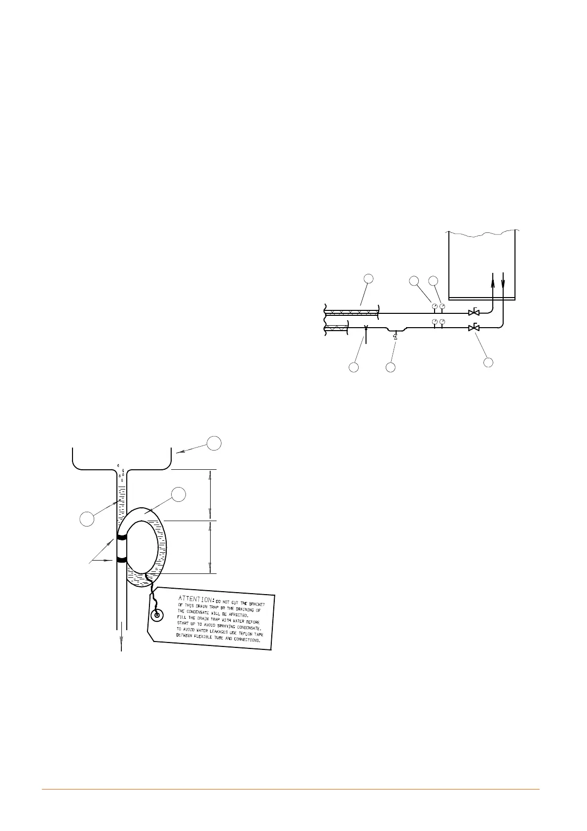
--- Condensate drain (Fig. c):
S Use galvanized steel, PVC or flexible polythene
tubing.
S Allow a 2% gradient towards the drain.
S There must be a drain trap (1) placed at least 20 cm
below the drain tray (2). In the units S13÷S23, Mxx
and Lxx the drain trap must be placed under the unit,
in the false floor.
S Fill the drain trap with water (3).
F i g . c --- C o n d e n s a t e d r a i n
BRACKET
to be
connected
by user
2
3
min.
1
20 cm
min.
10 cm
--- H u m i d i f i e r (optional):SeeEnclosure A.
--- H o t w a t e r (optional):
S Use copper or steel (Mannesmann) tubing.
S Insulate both tubes using Armaflex insulation.
5.3 -- Chilled water connections
(D and H only) --- ( F i g . d )
S Use copper or steel (Mannesmann) tubing.
S Place the tubing on supporting saddles (1).
S Insulate both tubes using Armaflex insulation (2).
S Place shut---off ball valves (3) at the conditioner inlet and
outlet to allow easy maintenance.
S It is useful to install a thermometer (4) and a manometer
(5) at the conditioner inlet and outlet.
S Install a water drain tap (6) at the lowest point in the cir-
cuit.
S Join the threaded water connections. It is recommended
to use hemp and paste to get a reliable pressure ---tight
joint.
S Fill the circuit with water/glycol (see Fig. d).
Air
1 6
3
4 5
2
conditioner
F i g . d --- C h i l l e d w a t e r c i r c u i t
5.4 -- Cooling water connections (W, F and H only)
The unit must receive cooling water as follows:
a) from an external cooling water source, in open circuit
(para. 5.4.1 and Figures in Enclosures).
b) using a Dry cooler, in closed circuit (para. 5.4.2).
S Connect the piping as shown in Enclosures D.
S It is advisable to use hoses to be connected, with
3---piece joints, to the condenser water inlet and outlet
couplings.
S IMPORTANT: fit a standard strainer on the inlet water pip-
ing.
S Place shut---off ball valves at the conditioner inlet and
outlet to allow easy maintenance.
S It is advisable to install a water drain system at the lowest
point in the circuit.
S Fully drain the piping before connecting it to the air con-
ditioner.
5.4.1 --- Notes for open circuit applications
S Use the unit with mains or well water.
DO NOT USE WATER FROM AN EVAPORATIVE COOL-
ING TOWER UNLESS THE FILLING WATER HARD -
NESS IS CONTROLLED.
S The water pressure must be 2 --- 10 bar (if this is not so,
contact the Technical Support Department).