12
English
Liebert HPM --- A/W/F/D/H
6 --- Electrical connections
6.1
-- Electrical connections
1) Before proceeding with the electrical connections, en-
sure that:
S all electri cal components are undamaged;
S allterminalscrewsaretight;
S the supply voltage and frequency are as indicated on
the unit.
2) Power supply cable connections:
S Connect the cable to the Line inlet terminal board.
S Usethecablesizedefinedaccordingtotheflow,the
supply voltage and the installation type.
S Thesystem/linecableprotectionistobearrangedby
the customer. Use a protection with differential
switch. If the system is equipped with EC fans, use
aBtypeswitch.
S Do not fit the supply cable in the raceways inside the
machine electric board.
S Use multipolar cables with sheath (CEI20 ---22) only.
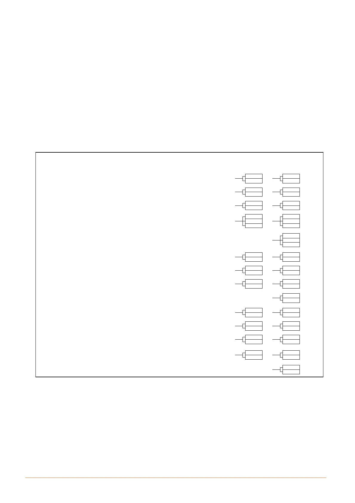
3) Wiring connec tions (Fig. f):
S Connections for remote on---off and hot water con-
sent must be done by the installer.
S According with compressor running, two terminals
for the opening of a water solenoid valve are avail-
able, by installer (W/H units).
S The General Alarm terminals allow remote alarm sig-
nalling.
4) In case of short circuit, check the sticking of the involved
switch and possibly replace it.
See electrical data in Enclosures B: Technical data
tables.
Fig. f --- Electrical connections
clogged filter (CF)
(CLOSE = OK)
remote on ---off
(CLOSE = ON)
smokestat firestat (AAP)
optional (CLOSE = ON)
water leakage (LWD)
GENERAL ALRM
(400, 401 NC = alarm or unit off)
operating fan
(CLOSE = ON)
operating compressor
(CLOSE = ON)
user alarm
(CLOSE = OK)
freecooling relay enabling, F/D/H only
(CLOSE = ON)
chilled water thermostat enabling,
D version only (CLOSE = compressor ON)
water solenoid valve enabling (by installer) before compressor
i n t e r v e n t i o n , W / H u n i t --- 2 4 V a c --- 1 A m a x
operating compressor 2
(CLOSE = ON)
water solenoid valve enabling (by installer) before compressor 2
i n t e r v e n t i o n , W / H u n i t --- 2 4 V a c --- 1 A m a x
WARNING
(300, 301 NC = warning or unit off)
only on units with EC fan
53
52
61
63
105
106
53
51
400 (NC)
401 (C)
402 (NO)
70
71
72
73
61
62
580
369
83
84
AUXILIARY TERMINAL BOX
(Cooling + Electr. heating + Humidification)
22
0
1 compressor 2 compressors
020
366
1
33
105
106
86
84
400 (NC)
401 (C)
402 (NO)
70
71
72
73
86
030
580
369
710
720
351
355
300 (NC)
301 (C)
302 (NC)
76
77
353
354
6.2 -- Fan connections
The fan is electrically feeded by 1 or 2 autotransformers that
are connected in order to obtain the nominal air flow and the
External Static Pressure (ESP: 20 Pa for Under and 50 Pa for
Over).
To change the factory connection proceed as follow:
--- identify the unit’s aeraulic graph in the Product Docu-
mentation;
--- choose the curve’s point where both the air flow and the
static pressure are the most suitable for the installation;
--- check the factory fan blocks connection and correct it, if
necessary (see electrical diagram);
--- choose the new output fan connections and connect the
wires to the relevant blocks.
6.3 -- Protection degree IP2x check
After whole of t he connect ions and insta llatio n wo rks, com-
prising ceiling elements (plenum, ducting) and floor ele-
ments (base frame), check and verify the protection degree
IP2x (protection against finger access, std. IEC 60364---1) at
the boundary of the air conditioner.
6.4 -- Protective features of EC fan
The
EC fan has been provided with the following protective
features:
S Over temperature of electronics
S Over temperature of motor
S Locked rotor protection