3
English
Liebert HPM --- A/W/F/D/H
For A and D units
Outdoor temperature: lower limit
Excee d ing of winter lower limits will temporar il y caus e a comp r es s o r
stop.
down to + 10° C
from +9° C to
--- 2 0 ° C
b e l o w --- 2 1 ° C
standard unit VARIEX required
Consult HPAC Tech-
nical Sales Support
Outdoor temperature: higher limit
This limit is determined by coupl ed condenser model. Exceeding of this
limit (or a lack of maintenance), will caused a compress or stop by HP
safety thermostat. Reset to normal operation can only be carried out
manuall y.
Relative position room unit vs. remote condenser
F r o m unit to cond ens-
er max distance
up to 30 m
equivalent length
from 30 to 50 m
equivalent length
F r o m unit to cond ens-
er max geod etic
heig ht ( 1 ) (2)
from 20 m to --- 3 m from 30 m to ---8 m
Requi r em ents
Pipe diameter see Tab. c see Tab. c
Oil traps on vertical
line of gas refrige-
rant
every 6 m, ma x every 6 m, ma x
Extra oil charge see Tab. 8 see Tab. 8
Variex installation suggested mandatory
Condenser design oversized +15%
Hot gas reheat allowed NOT allowed
Additional non
return valve on deli-
very lin e, at 2 m
from compressor
not
necessary
mandatory
For W, F and H units
Water or mixture temperature to condenser,
lower limit (other information par. 5.4)
min. 5° C
For F, D and H units
Chilled water circuit
inlet water t emperature min. 5°C
water pressure max. 16 bar
Max. differential pressure s on th e modulating valve
(2 or 3 ways)
--- Max. differential pressure through the closed valve: Δp
cv
--- Max. differential pressure across the valve for modulating service:
Δp
ms
Model s
Δp
cv
(kPa) Δp
ms
(kPa)
S1GxF/D/H 300 300
S2ExF/D/H 300 300
S2GxF/D/H 300 300
M2HxF/D/H 300 300
M3FxF/D/H 175 175
M3GxF/D/H 175 175
M4ExF/D/H 175 175
M4HxF/D/H 175 175
M5BxF/D/H 175 175
M5CxF/D/H 175 175
M5DxF/D/H 175 175
L8Fx F/D/H 150 200
(1) Positive difference in height: condenser above conditioner
(2) Negative difference in height: condenser below conditioner
Other information in para 5.3.
1.12 -- Noise level limits
The sound pressure level in free field at 1.5 m height and 2 m
in front of the air conditioner , with compressor and fan in op-
erations, is less than 70 dBA for all models.
2 --- General description
2.1 --
Direct expansion units
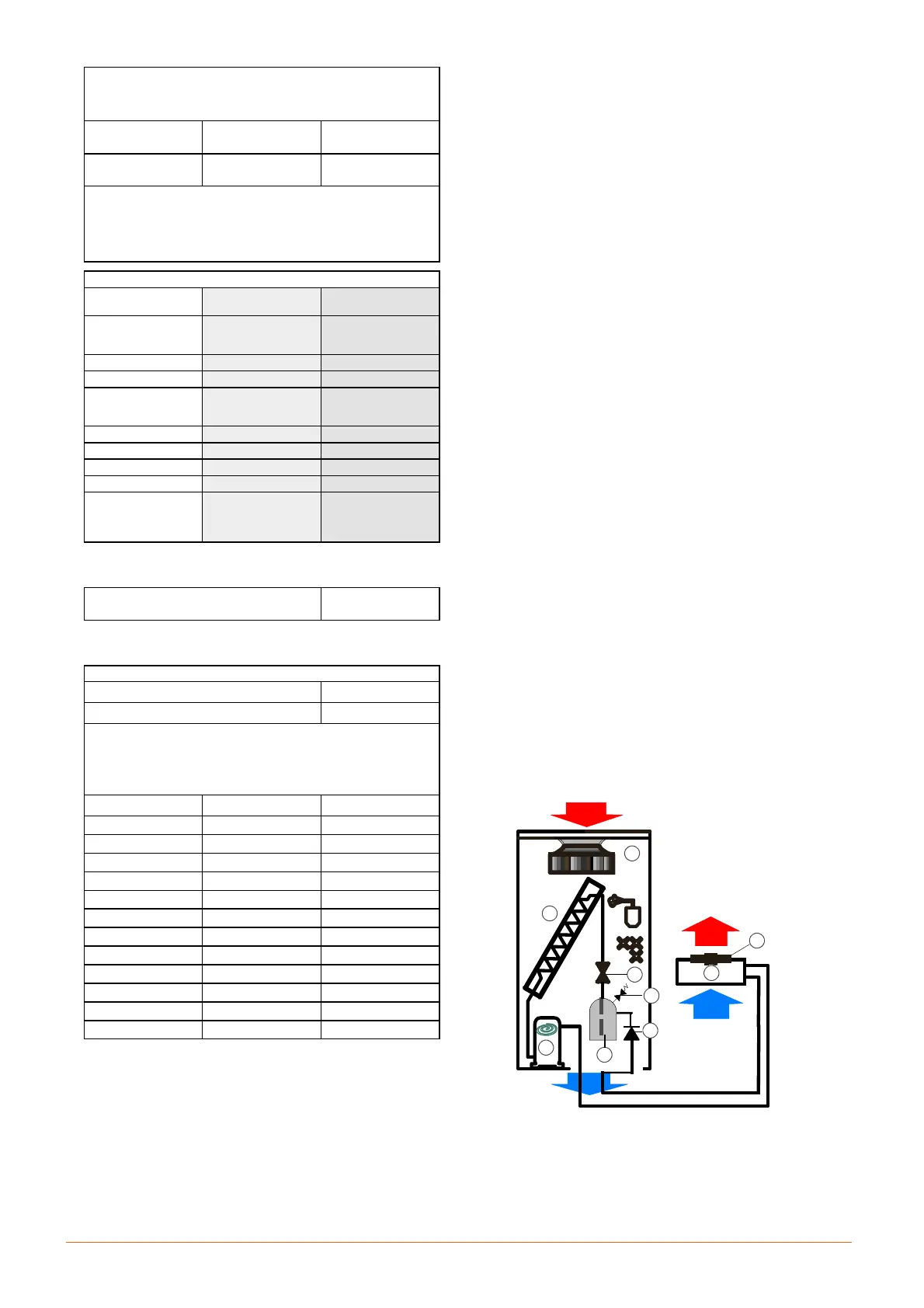
2.1.1 --- Refrigeration circuit
All models are provided with a single refrigeration circuit, M
and L ranges present also double circuit units. The com-
pressor (1) pumps the hot gaseous refrigerant into an o ut-
door air---coo led condenser (2). The liquefied refrigerant ar-
rives to a liquid receiver (3) that ensures a constant and even
refrigerant flow to the thermostatic expansion valve (4) and
then arrives to the evaporator (5). Here the refrigerant,
thanks to the heat --- exchanged with the room air moved by
the fan (6) --- evaporates and returns to the compressor (1);
from this, the refrigerant begins a new refrigeration cycle. To
maintain the correct refrigerant discharge pressure, the
speed of th e m otor f an (8 ) is con trolled (on---of f or propor-
tional mode).
Shut---off valves are provided as standard to assist wit h
routine maintenance.
The compressor (1) has abuilt---in non---returnvalve toavoid
return of liquid ref rigerant from the conden ser in summer-
time, thus protecting the compressor from undesired refri-
gerant slugging during the start up. A second non---return
valve (7) is recommended to avoid --- in wintertime --- refri-
gerant migration from the liquid pipes and the receiver (3) to
the cond en ser (2), th at sh ould b e resp on sib le of low pres-
sure intervention at the start---up of compressor.
For safety reason, a relief valve (9) is installed on the liquid
receiver (3); this valve is equipped with flanged connections
so that the refrigerant may be discharged to the outside.
2.1.2 --- Version A
External air---cooled condenser (2)
The units may be connected with a w id e range of our con-
densers in standar d or low noise versio n. For technical data
and performance, refer to the relevant technical documenta-
tion.
Note 1. Units and exter nal condensers are supplied separ-
ately.
Note 2. The room unit refrigeration circuit is pressurised
with helium at 3 bar and the condenserrefrigeration circuit at
2bar with dry air.
Note 3. The customer is resp onsible for making connec-
ti ons bet ween the Uni t and th e externa l c ondenser a nd for
charging with refrigerant (standard R410A) and oil, when re-
quest.
SxxUA
MxxUA
LxxUA
Units
1
2
4
8
5
6
3
9
7
2.1.3 --- Version W
Wate
r---cooled condenser
These units are provided with one very efficient stainless
steel brazed---plate water---cooled condenser (2). The co n-