13
English
Liebert HPM --- A/W/F/D/H
S Short circuit at the motor output
With any of these failures, the motor stops (electronically –
no potential separation), the status relay is released.
NO automatic restart. To reset the alarm, power supply has
to be switched off for min. 20s once motor is at standstill.
S Mains under---voltage detection:
if mains voltage falls below 3ph/290Vac (typical value)
for 5s minimum, motor will be swithed off (only by elec-
tronics, no potential separation), status relay is released.
If mains voltage returns to correct values, the motor
will restart automatically.
S Phase failure recognition:
if one phase failes for 5s minimum, motor will be
switched off (only by electronics, no potential separa-
tion), status relay is released.
If all 3 phases return to correct values, the motor will
restart automatically within 10 ---40s.
The power supply for an external speed setting potentiomet-
er is short---circuit protected.
Motor is overload---protected via motor current limitation.
Warning! Leakage current of the motor is 7 mA roughly.
7 --- Start-up
7.1 -- First start--up (or after long standstill)
TO PREVENT COMPRESSOR DAMAGE THE C RANK-
CASE(S) MUST BE PREHEATED FOR AT LEAST 4 HOURS
BEFORE CONDITIONER START---UP (FAILURE TO DO SO
INVALIDATES THE GU ARANT EE) .
Start the air co ndit ioner as follows:
1) Open all valves in the refrigeration circuit according to
the instruction label attached to the valve.
2) W, F and H only: Open all valves in the water circuit ac-
cording to the instruction label attached to the valve.
3) Ensure that the refrigerant charge is correct (see Chap.
4).
4) Using a leak detector, verify that there are no refrigerant
leaks. If there are any, then repair the leak and recharge
as described in Chap. 4.
5) At least 4 hours before start---up, close the main switch
and miniature circuit breaker for transformers’ protection
on the electrical panel.
In the “iCom” control system factory setting the stand
alone mode is standard. The stand alone mode givesthe
possibility of turning on the unit simply rotating the main
switch on the electric panel. The yellow LED on theiCom
case will light after turning on the unit, because of the
presence of electric power.
If the LED does not light up:
S check the electric panel power supply;
S check the protection devices (e.g.: thermal
switches);
S check the fuses.
6) V erify the operation of the crankcase heater.
7) Check that there are no water leakages.
8) D and H only: Bleed all air out of the chilled water circuit
using the bleed valve on the chille d water coil.
9) If an external condenser or Dry cooler is installed, start
it by supplying power to it.
10) Close all MCBs on the electrical panel.
11) Check the supply voltage on all phases.
12) Check the supply voltage on all phases for the external
condenserorDrycooler,iffitted.
13) ENSURE THAT THE COMPRESSOR HAS BEEN PRE-
HEATED FOR AT LEAST 4 HOURS BEFORE START-
ING THE UNIT.
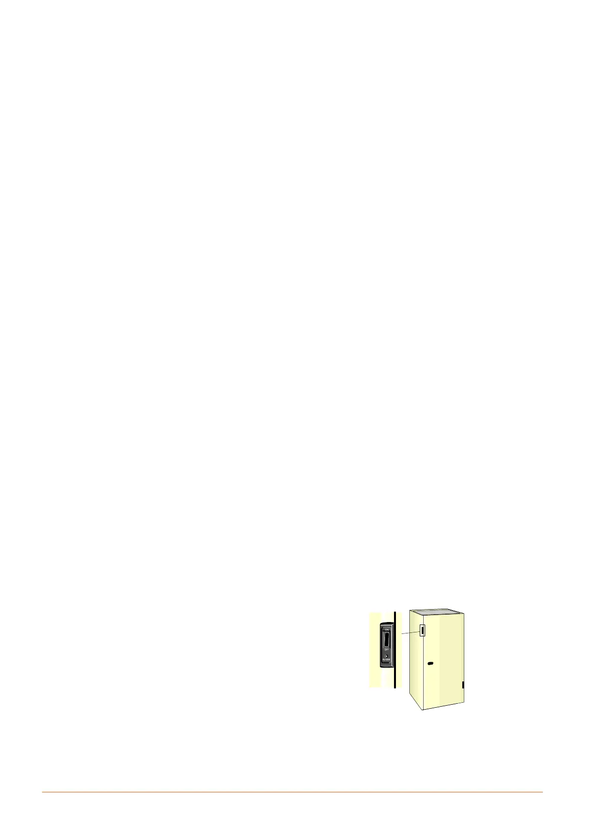
14) Start the unit by pressing ON OFF (see Fig. g).
15) Check the electrical absorption of all components (see
Chap. 6).
16) Check the electrical absorption of the external condens-
er/Dry cooler, if fitted.
17) IMPORTANT --- If the compressor makes a loud and
unusual noise IT IS NECESSARY TO INVERT the
electrical connections of the phases supplying the
corresponding scroll compressor, which accepts
only one direction of rotation.
18) Ensure that the fans rotate in the c
orrect direction (see
arrow on fan).
CAUTION: risk of contact with rotating devices.
19) Ensure that all control system settings are correct and
that there are no alarms (see Control manual).
20) W, F and H only:Verify thewaterflow.
21) W, F and H only: For closed circuit units ensure that the
water pump starts when the compressor starts.
22) Verify the Fresh Air Intake operation (if fitted).
23) Once the system is operating under load, check the
various components, as follows:
S V erify that the fans are operating properly.
S Ensure that the temperature and relative humidity
are being cont rolled, and that the humidifier (option-
al) and heating steps (optional) operate when re-
quired.
S Ensure that the compressor operates when required.
S D and H only: Ensure that chilled water valve oper-
ates when required.
S Ensure that the fan operation contro ller on the ex-
ternal condenser/Dry cooler (if fitted) is calibrated
correctly, and that it controls the fan operation.
7.2 -- Starting and stopping
S ALWAYS ENSURE THAT EACH CRANKCASE HAS
BEEN PREHEATED.
FOR BRIEF STOPPAGES KEEP THE SUPPLY TO THE
CRANKCASE HEATER.
Turn on the unit operating on the ON/OFF switch placed on
the left case of the unit (Fig. g). If the ON/OFF remote device
is not installed, the green LED on the iC om case will light up
together with the LED placed below the ON/OFF switch. The
fan starts immediately (the fan always works when the unit is
ON); after 2 minutes the regulation is activated, so the co ol-
ing (compressor), heating (electric heaters), humidifying
and dehumidifying devices can start.
Adjust the set---point as indicated in Control manual.
Stop the unit putting the ON/OFF switch in OFF.
7.3 -- Automatic restart
If desired, the unit will automatically restart on the return of
power afte r a supply interruption (see C o nt r o l manual).
If the power interruption is expected to be of several hours,
to avoid an automatic cold restart of the compressor stop the
unit before the black---out and, on the return o f power, allow
the compressor to preheat before restarting the unit.
F i g . g --- O n --- O f f s w i t c h