15
English
Liebert HPM --- A/W/F/D/H
9 --- Calibrations & Regulation
(a
t start---up)
The air conditioner has already been factory---tested and
calibrated, but it is very important to check, at start---up, the
superheating of thermostatic valve (all versions) and the
by---pass hot gas valve (F/D/H/KA/KW).
See Tab. 6 and Tab. 7 (Enclosed B) that show all valves.
S The air conditioner has already been factory.
S For calibrations of instruments installed on the external
condensers/Dry coolers refer to the relevant manual.
S For control system calibrations refer to Control manual
(to prevent erratic operations do not use temperature
and rel. humidity set points/proportional bands which
differ excessively from the Standard Settings).
9.1 -- Setting the thermostatic expansion valve
THIS OPERATION MUST BE PERFORMED BY AN
EXPERI-ENCED REFRIGERATION TECHNICIAN.
The valve has been factory preset and, if neces sary , should
be reset as follows:
1) IMPORTANT: Ensure that the instructions in Chap. 4
have been carried out.
2) Allow the compressor to operate for 15 mins.
3) Measure the superheat as follows:
a) Place a contact thermometer on the tube exiting the
evaporator;
b) Connect a manometer (by a tube of max. 30 cm) to
the compressor suction valve.
c) The overheating is the difference between the refri-
gerant saturation temperature corresponding to the
pressure read on the manometer and the real tem-
perature read on the thermometer.
4) The superheat must be 6 ---7 K; if not, set the expansion
valve as follows:
a) Remove the protective cover;
b) Turn the adjustment screw by 1/4 turn only;
c) Wait 10 minutes.
d) Measure the superheat and repeat the operation if
necessary.
N.B.: If the superheat is too low (compressor cool to the
touch) the screw must be turned in a clockwise direction.
If the superheat is too high (compressor hot to the touch)
the screw must be turned in a counterclockwise direc-
tion.
9.2 -- Adjustment of the hot gas injection valve
as antifreeze mode and partial control of
the
capacity (F, D, H and Constant)
THIS OPERATION MUST BE CARRIED OUT BY AN EX-
PERT REFRIGERATION TECHNICIAN.
9.2.1 --- Features
This valve is installed int some special versions (see relevant
refrigeration circuits). It enables a partial control of the evap-
orating pressure, so as to av oid evaporation temperatures
lower than zero degrees centigrade and thus any ice forma-
tion (chilled water side), even with low temperatures of the
return air. It injects hot gas exiting the compressor before the
evaporator t hrough the gas---li quid mixer, so as to keep the
pressure higher than the set value. See the refrigeraton dia-
gram.
9.2.2 --- Adjustment
The min. evaporating pressure is kept by calibrating the
valve as follows.
S Drastically reduce the conditioner air delivery.
S Check by a precise pressure gauge the evaporating
pressure and the relevant saturation temperature.
S Adjust the valve acting on the adjustment screw, so that
it intervenes when the evaporation temperature has de-
creased to 2° C.
S Then check the correct operation of the thermostatic ex-
pansion valve.
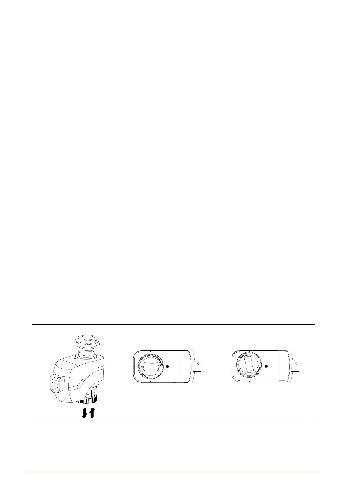
9.3 -- Chilled water valve (F, D and H only)
The 2---way (F) or 3---way (D/H) valve controls the chilled wa-ter
flow and operates as follows (Fig. j):
S When the valve is fully open (i.e. max. chilled water flow)
the actuator slot is set to ’1’.
S When the valve is closed (i.e. no chilled water flow) the
actuato r slot is set to ’0’.
The valve running time is set to the value specified in the
Control Manual.
Note 1: In the unlikely event of control system failure, the
valve can be manually controlled by means of the rotary
knob. It can be used to drive the actuator into any position
between 0 and 1.
Note 2: When actuator stem is completely down, the valve is
open and chilled water coil is supplied.
Fig. j --- Position of the chilled water valve actuator (for 2 or 3---way valve)
0
1
Position indicator on
0 =CLOSEDvalve
( 3 --- w a y v a l v e : b y --- p a s s o p e n )
Position indicator on
1 =OPENvalve
( 3 --- w a y v a l v e : b y --- p a s s c l o s e d )
0
1