Refrigerant and h
ydraulic connections
D---5 Liebert HPM --- A/W/F/D/H
English
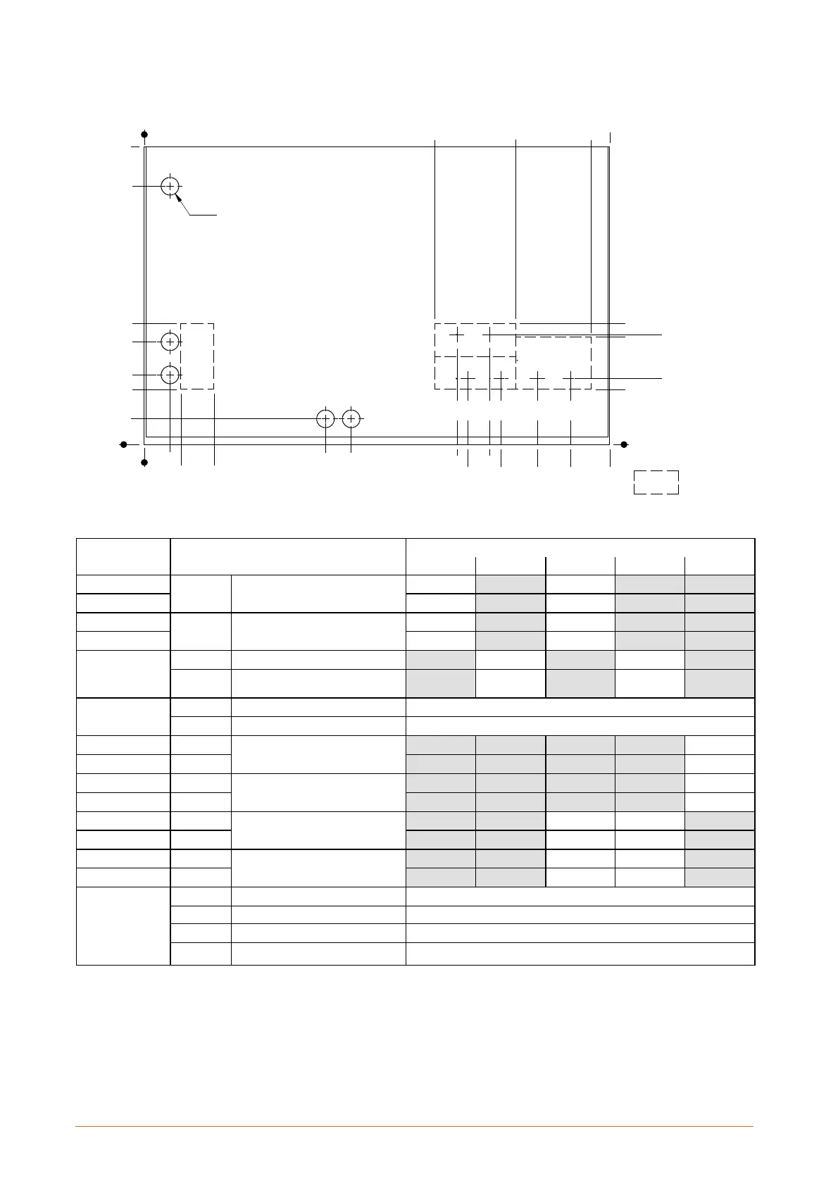
Fig. 5 --- Refrigerant, water and electrical connections Liebert HPM M3F ... 5B, single circuit --- Plan view
UNIT FRONT
no. 5 holes 48
IFC
D+H
OFC
D+H
IFC
F
OFC
F
IWC1
/IL1
OWC1
/OG1
EC
HD
HF
OHW
IHW
CD
0
70
150
190
280
330
705
850
0
1285
1505 1710
1750
0
150
180
293
300
330
0
70
100 180
800 870 1345
1375
1435
1465 1565 1655 1750
Precut holes
Models Unit Con nection
Version
A W D H F
M4E
IL1
Refrigerant liquid line inlet 1*
OD 16 mm OD 16 mm
M 4 E --- 5 B
OD 18 mm OD 18 mm
M3G
OG1
Refrigerant gas line outtlet 1*
OD 18 mm OD 18 mm
M 4 E --- 5 B
OD 22 mm OD 22 mm
M 3 G --- 4 E --- 5 B
IWC1
Water to condenser 1 inlet --- ISO 7/1 Rp 1¼ Rp 1¼
OWC1
Water from condenser 1 outlet
ISO 7/1
Rp 1¼ Rp 1¼
Mxx
IHW
Hotwaterinlet(opt.)
OD 22 mm
OHW
Hot water outlet (opt.)
OD 22 mm
M3G
IFC (F)
Water inlet to Freecooling --- ISO 7/1
Rp 1¼
M 4 E --- 5 B
IFC (F)
Rp 1½
M3G
OFC (F)
Water outlet from Freecooling
ISO 7/1
Rp 1¼
M 4 E --- 5 B
OFC (F)
Rp 1½
M3G
IFC (D+H)
W ater inlet to Dualfluid --- ISO 7/1
Rp 1¼ Rp 1¼
M 4 E --- 5 B
IFC (D+H)
Rp 1½ Rp 1½
M3G
OFC (D+H)
Water outlet from Dualfluid
ISO 7/1
Rp 1¼ Rp 1¼
M 4 E --- 5 B
OFC (D+H)
Rp 1½ Rp 1½
Mxx
CD
Condensate drain
ID 20 mm
HF
Humidifier feed (opt.) --- ISO 7/1
R½
HD
Humidifier drain (opt.)
ID 22 mm
EC
Electrical power supply
Hole 48 mm
* Connection size only. The dimension of the connecting pipe depends on unit model and refrigerant, see Tab. c on para. 4.1.2.