Refrigeration circuits
E --- 2 0 Liebert HPM --- A/W/F/D/H
English
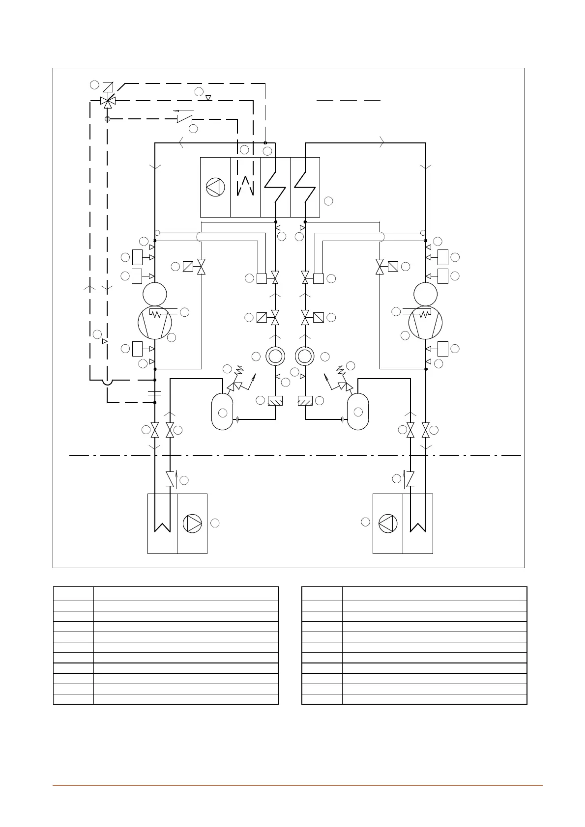
Fig. 20 --- Refrigerant diagram Liebert HPM L8F---L9H A (R410A)
SUPPLY LIMITSUPPLY LIMIT
CONDENSING UNIT CONDENSING UNIT
MC MC
2
1
2
1
44
44
5
5
6
6
6
6
6
6
6
7
7
8
8
9
9
10
10
11
12
12
12
13
13
14
15
15
16
1717
13
13
FG FG
1818
19 19
16
6
3
6
3
6
ONLY WITH REHEATING COIL OPTION
POS. DESCRIPTION
1 Compressor
2 Crankcase heater
3 High pressure switch (HP)
4 Air cooled condenser
5 Liquid receiver
6 Access valve
7 Safety valve
8 Filter dryer
9 Sight glass
10 Thermostatic expansion valve
POS. DESCRIPTION
11 Hot gas solenoid valve (optional)
12 Check valve
13 Shut---off valve
14 Reheating coil (optional)
15 Evaporator
16 Low pressure switch (LP)
17 Shut---off solenoid valve
18 Hot gas valve injection
19 On/off pressure switch for hot gas valve injection
20 ---