Vertiv | Liebert LVC | User Manual 15
Installation
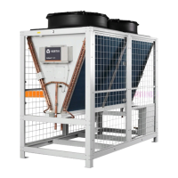
Table 1-3 Side by Side Installation Space Requirement (unit: mm/inch)
Model L1 L2 W H1 H2
Gas pipe
outer dia.
Liquid pipe
outer dia.
LVC088 /
LVC106
203 /
7.9”
115 /
4.5”
550 /
21.7”
251 /
9.9”
223 /
8.8”
28 /
1.1”
22/
0.9”
LVC140
203 /
7.9”
115 /
4.5”
625 /
24.6”
460 /
18.1”
427 /
16.8”
28 /
1.1”
22/
0.9”
LVC152 /
LVC170
203 /
7.9”
115 /
4.5”
625 /
24.6”
224 /
8.8”
195 /
7.7”
28 /
1.1”
22/
0.9”
2. Identify the outer diameter of gas and liquid pipe: Refer to installing unit pipes in ‘Liebert Indoor Air
Conditioner User Manual’ for pipe outer diameter.
3. Identify the condenser installation height: Refer to installing unit pipes in ‘Liebert indoor Air Conditioner
User Manual’ for installation height.
4. Install the pipes: Install the pipes according to the actual situation and national codes and standards.
• If the indoor unit is dual system unit, it is required to connect the gas and liquid pipe of the same
indoor unit No.1 system and condenser No.1 system, connect the gas and liquid pipe of same indoor
unit No.2 system and condenser No.2 system.
• If indoor unit is a single-system unit, it is required to number the condenser and indoor unit respec-
tively. This will avoid gas and liquid pipe connection error. Such as No.1 indoor unit connected with
No.1 condenser No.1 system, No.2 indoor unit connected with No.1 condenser No.2 system.
• According to the actual situation, plan the condenser installation location and reduce the distance
connected with the pipe of indoor unit.
1.4.2. Connecting External Power
1. Identify the cable specications
A condenser has two systems. It is required to the condenser No.1 system and No.2 system to powered supply
respectively. Select the appropiate power supply cables (L1/L2/L3/N/PE) and control cables (two core wires) of
the condenser according to the Full Load Current and the Installation Distance as shown in Table 2-4.