Vertiv | Liebert LVC | User Manual 21
Spray Cooling Module (Optional Component)
3.3.2. Water Filter
To ensure the normal operation of spray system, it is must to install water lter in the inlet and outlet of water
softener. Filtering level ≤ 150m.
3.4. Electrical Control Box of Spray Cooling Module
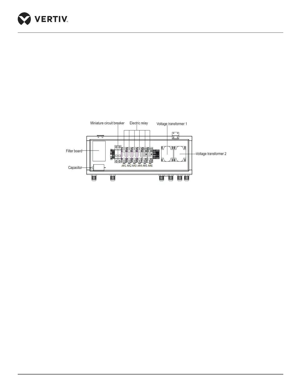
The main components of electric control box include miniature circuit breaker, electric relay, capacitance, lter
band and voltage transformer. The appearance and position of electrical control box are shown in Figure 3-4.
Figure 3-4 Electrical Control Box of Spray Cooling Module
3.5. Pre-Commissioning (Trial running) of Spray Cooling Module
Spray cooling module pre-commissioning steps
1. After connecting the water pipe (refer to Section 3.3 ‘Pipeline Installation of Spray Water System’) to
pressure resistance, test the water pressure according to the requirement of the relevant specications.
2. Open the total water inlet valve, water lter and water softener, to conrm the softening water equipment is
operating normally.
3. Open the ball valve of spray cooling module as shown in Figure 3-4, then unscrew the drainage export of the
pump water inlet & outlet pipeline connected with the drainage export of No.1 & No.2 systems and pressure
gauge, then measure required the water pressure is between 0.5- 3.0 bar.
4. Remove the pressure gauge and tighten the drainage export and start troubleshooting of spray cooling
module.
5. Close the ‘Miniature circuit breaker’ of the spray cooling module of the condenser No.1 system and No.2
system as shown in Figure 3-4. Enter to the conguration menu interface of the control board, set the setting
value of the No.1 system and No.2 system parameters in the controller C44 to 1, and value of C45 to 1.
6. Take a trial run of the spray cooling module at least for 3min. It is required to observe the smooth operation