Vertiv | Liebert LVC | User Manual 22
Spray Cooling Module (Optional Component)
of the water pump and solenoid valve. Also observe the nozzle can spray out the water mist, and the spray
water pipe is not leaking.
7. Set the setting values of the No.1 system and No.2 system parameters in the controller C45 to 2 and
unscrew the Y-shape lter of the ball valve. Then, clean the lter screen to reinstall it.
8. Set the setting value of C45 to 0 to complete the trial running of spray cooling module.
• The power supply for the entire spray cooling module comes from No.1 system, so the
spray system of No.2 system is required to run separately, such that the No.1 system
does not get power o.
• Refer to 4.2 Operation Description of HMI for setting conguration.
3.6. Antifreeze Maintenance of Spray Water System
When the temperature is below 0°C, the water system pipe will be frozen, leading to frost damage the water
pipe, the water softener, the water lter, the pump and the ball valve. To avoid the damage, drain the water of
the spray water pipes and the spray cooling module before winter.
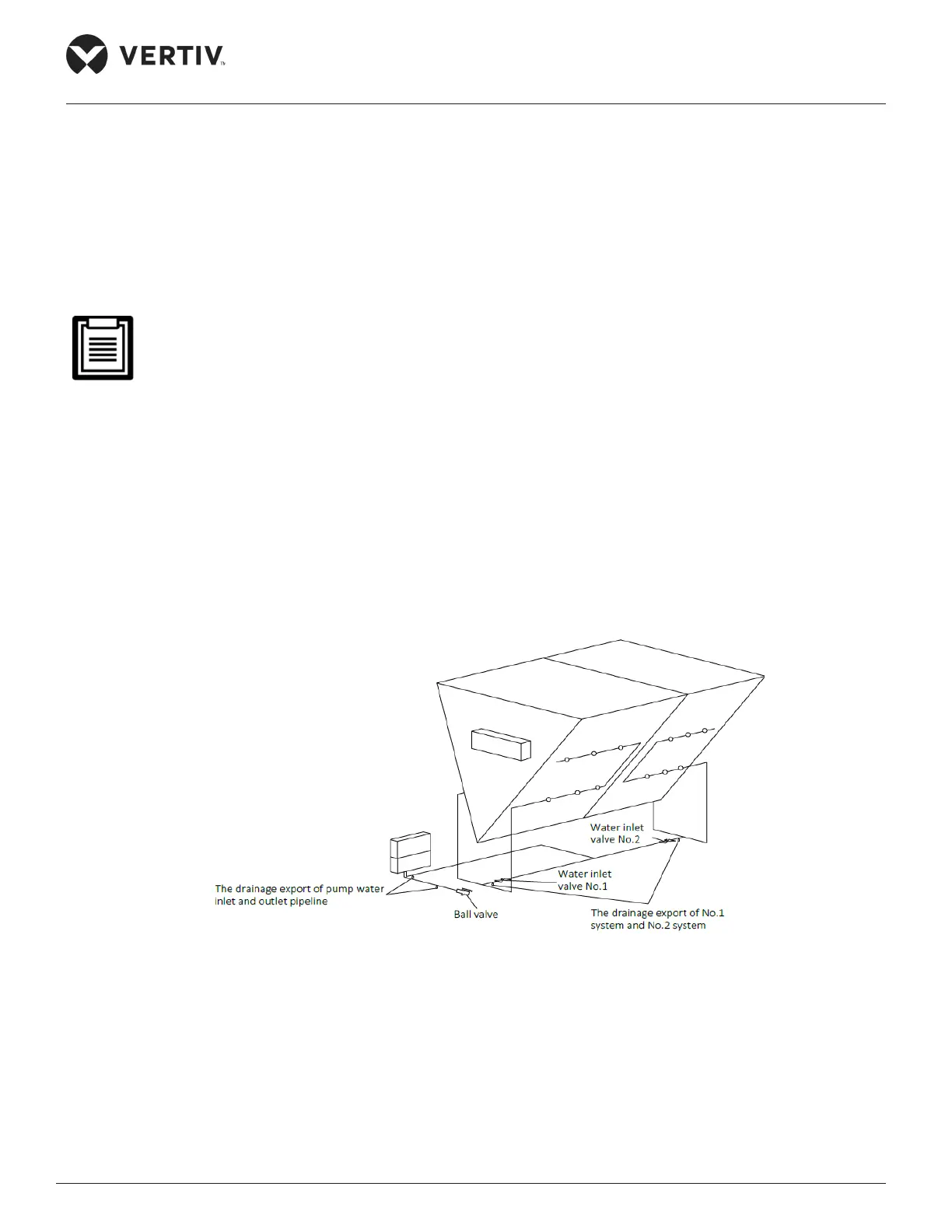
Figure 3-5 Drainage Export of Spray Cooling Module
3.6.1. Antifreeze Maintenance of Spray Cooling Module
Close the ball valve and miniature circuit breaker (see Figure 3-4) of the spray cooling module, unscrew the
drainage export of the pump water inlet and outlet pipe, unscrew the drainage export of the No.1 system and
No.2 system (as shown in Figure 3-5). Drain the water of spray cooling module, so that compressed air can be
used to blow the residual water.