Vertiv | Liebert LVC | User Manual 25
Application of Fan Speed Controller
Serial Number Function Description
C
Query the acquisition data in real
time
The congured parameter includes running pressure,
pressure controlling range, minimum output
frequency, maximum output frequency, fan number
and pressure sensor type, refrigerant type, jump
frequency 1, jump frequency 1 range, jump frequency
2, jump frequency 2 range, jump frequency 3, jump
frequency 3 range, the curve of frequency control,
manual mode, manual mode output frequency; or
resume the default values
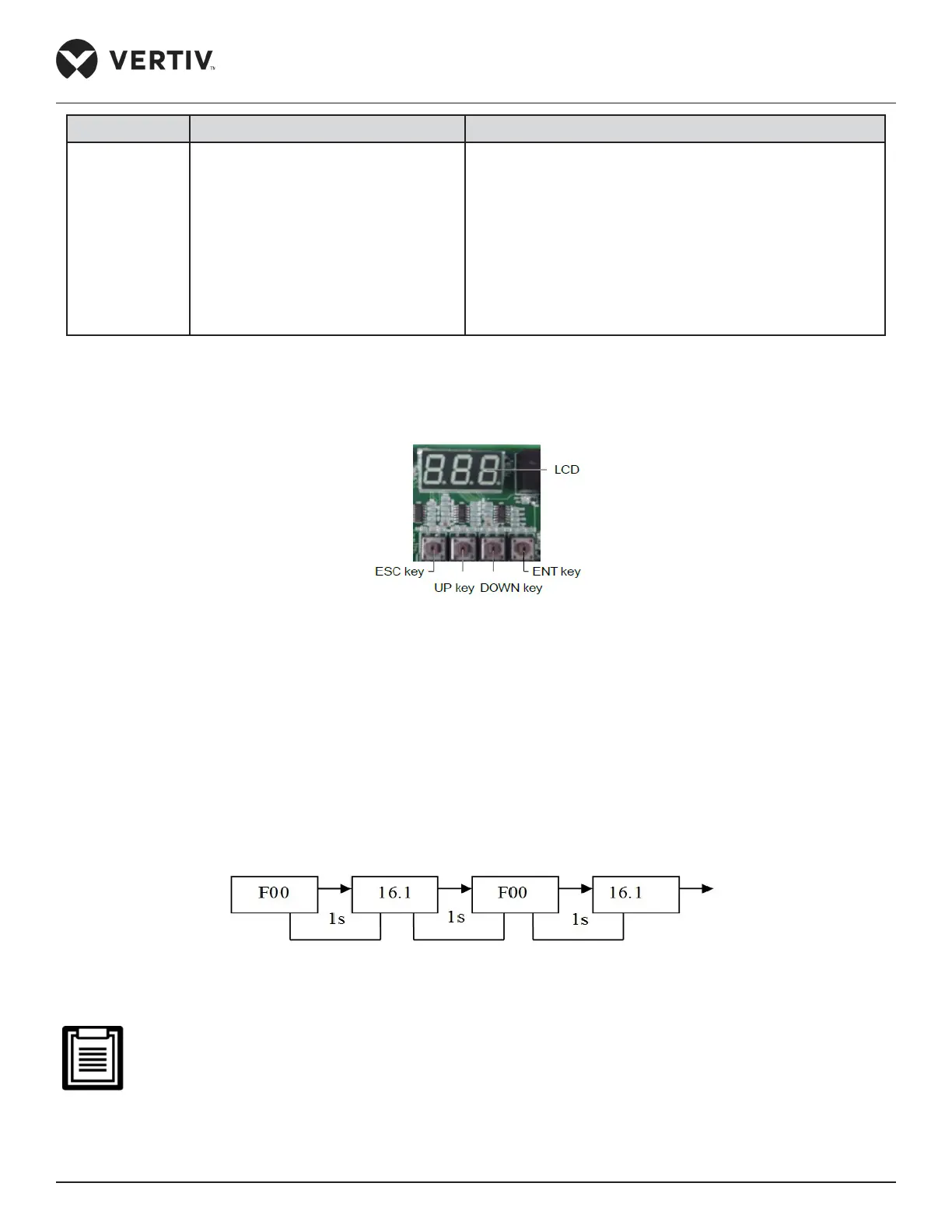
The keys and LCD are on the upper right corner of the fan speed controller board, as shown in Figure 4-1.
Figure 4-1 Keys and LCD
4.2. Operation Description of HMI
4.2.1. Initial Interface
The LCD will alternately display ‘F00’ (the maximum pressure logo) and the larger of condensing pressure 1
and condensing pressure 2 when the fan speed controller is powered on initially. The display order is shown in
Figure 4-2.
Figure 4-2 Display Order of the Initial Interface
• The “16.1” is only an example, and the actual value is determined by the sampling result