19Liebert PCW - UM - 273895 - 04.10.2018
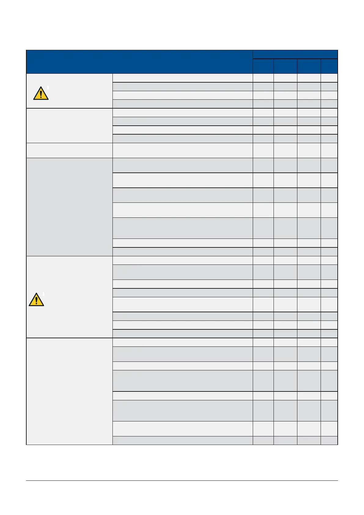
Maintenance schedule
COMPONENT
MAINTENANCE PERIOD EVERY
1
Month
3
Months
6
Months
1
Year
FANS
Attention, do not reach
into the fan while the fan
wheel is running.
Check for soiling, damage, corrosion, and proper xing. X
Check bearings noise. X
Measure the current and power consumption. X
Cleaning to preserve the function. X
AIR FILTERS
Check for soiling, damage, corrosion. X
Check state of lter. X
Clean or replace if necessary. X
Carry out controls more frequently in dusty environments. X
NEW AIR FILTER
(if installed)
see air lter. Clean or replace X
CONTROL SYSTEM
Check for proper and functionally correct installation and
surrounding conditions.
X
Check the function of the LEDs of the display’s control sys-
tem and the alarms.
X
Check the connections for electrical and mechanical func-
tion.
X
Check the functional elements (e.g. operational controls
and display devices).
X
Check the electrical/electronic and pneumatic input sig-
nals (e.g. sensors, remote controllers, command variable)
for compliance with nominal values.
X
Check control function, control signals, and safety chains. X
Adjust control function and control signals. X
SWITCH CABINET POWER
CIRCUITS
Attention, electrical cables
and electrical components
of the air conditioner are
under voltage.
Check the power supply on all phases. X
Check the connections for electrical and mechanical func-
tion.
X
Check the power supply at all terminals. X
Measure power consumption at all connected consumers. X
Set, adjust, and tighten the functional elements (e.g. opera-
tional controls and display devices).
X
Check safety equipment, e.g. thermal switch. X
Replace fuses (every 2 - 3 years) X
Check protective covers for completeness. X
CHILLED WATER CIRCUIT
Make sure there is no loss of water. X
Deaerate the cooling water circuit using the vent valve on
the top right hand side of the cooling coil.
X
Check that the cold water supply is ensured. X
Check the temperature and the pressure of the water on the
inlet and outlet side using thermometers and manometers
if installed
X
Check the proper function of the three - way valve. X
Make sure that the system is lled with the prescribed
amount of glycol and that there is no frost in the hydraulic
circuit.
X
In case water loss needs to be relled make sure the glycol
concentration is correct.
X
Check that the water circulation is in perfect order. X