S600D
12
Maintenance bypass
The UPS is equipped with a second bypass circuit, known as the maintenance bypass, which provides a safe
working environment for the engineers to carry out regular maintenance or repair the UPS system, while providing
unregulated mains supply to the loads. The maintenance bypass can be activated manually selected by closing the
maintenance bypass switch, and disconnected by setting the switch to OFF.
UPS Power Supply Switch Configuration
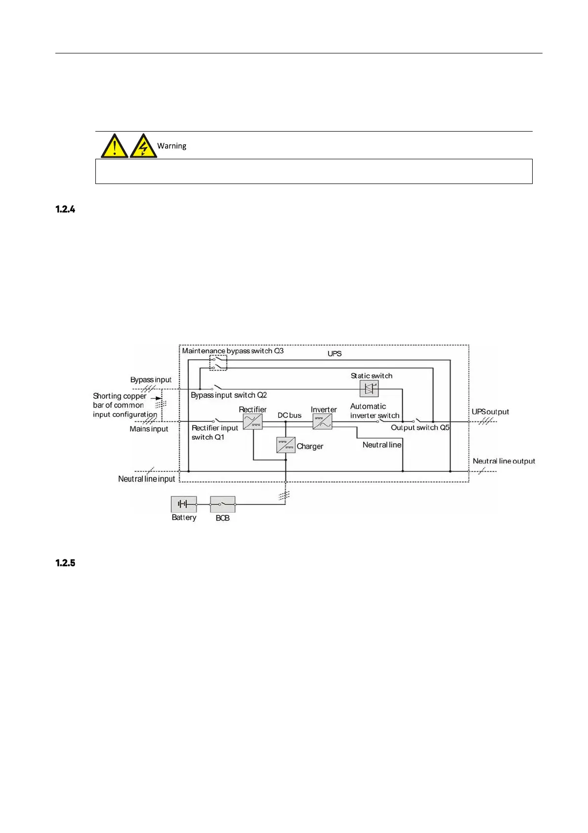
Figure 1-2 illustrates the block diagram of the UPS module. The UPS may be connected in split bypass (where the
bypass is supplied by a separate mains input source) or common input configuration. In the split bypass
configuration, the static bypass and maintenance bypass share the same independent bypass power supply. Where
a separate power source is not available, the input supply connections of the bypass input switch (Q2) and rectifier
input switch (Q1) should be linked together (these terminals are linked before delivery) so that the bypass input and
rectifier input use mains power from the same source.
During the normal UPS operation, all switches should be closed, with the exception of the maintenance bypass
switch Q3.
Figure 1-2 UPS power supply switch configuration
Battery Circuit Breaker (BCB)
The external battery shall be connected to the UPS via the BCB. The BCB box is an option that must be installed
close to the battery.
1.3
Parallel System
Up to four UPS modules may be parallel-connected to form a parallel system and increase the system capacity and
reliability. The load is shared equally between the parallel connected UPS modules.
Also, two UPS modules or parallel system may be used to form a dual bus system (LBS). Each UPS module or
parallel system has an independent output. Output synchronization is achieved through the LBS cable, thus
enabling seamless load transfer between the two systems.