S600D
26
Chapter 3 Electrical Installation
This section principally introduces the UPS electrical installation procedures, including the power cable and signal
cable connecting procedures and methods.
Once the mechanical installation procedure is complete, it is necessary to connect the power and signal cables to
the UPS. All signal cables, whether or not they are shielded, must be kept away from the power cables.
3.1
Connecting the Power Cables
System Configuration
The system power cable dimensions shall meet the following requirements:
UPS input cable
The UPS input cable dimension differs depending on the UPS power ratings and input AC voltages, provided that it
meets the requirement of maximum input current, including the maximum battery charge current, see Table 3-1.
UPS bypass and output cable
The UPS bypass and output cable size differs depending on the UPS power rating and output AC voltages, provided
that it meets the requirement of nominal output or bypass current, as shown in Table 3-1.
Battery cable
Each UPS is connected to the respective battery positive pole, negative pole and neutral line by three cables . The
battery cable dimension differs depending on the UPS power ratings, provided that it meets the battery discharge
current requirement when the battery voltage nears the EOD level, as shown in Table
3-1.
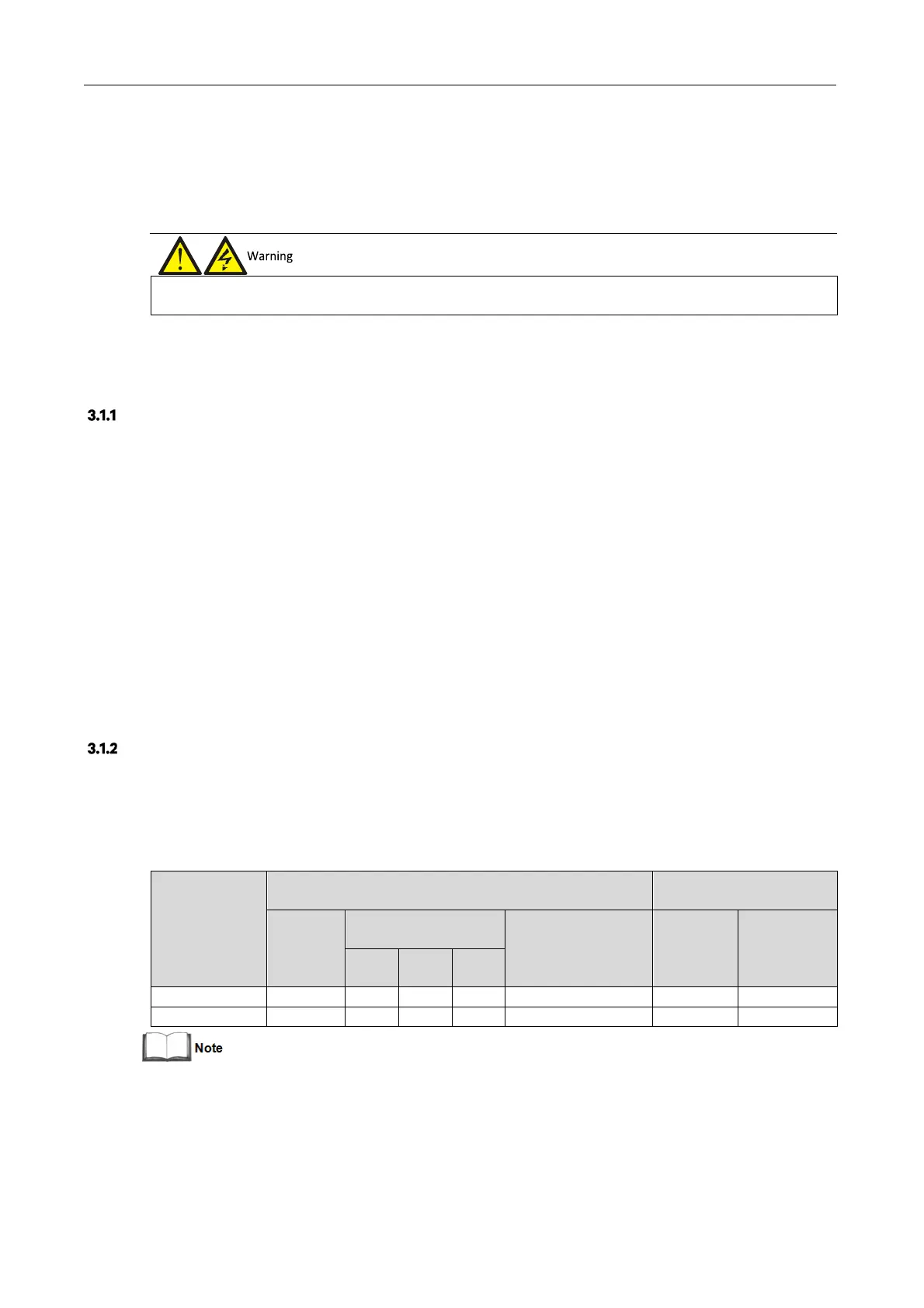
Maximum Steady State AC and DC Currents
The power cable must be selected according to the current and voltage values indicated in Table 3-1, as well as the
local wiring regulations, as well as taking environmental conditions (temperature and physical media) into
consideration; refer to Table 3B in IEC 60950-1.
Table 3-1 Max. steady state AC and DC currents