S600D
32
output copper shorting bars (oA-oB-oC), oN and the load. Refer to Table 3-1 for the tightening torque values. Make
sure that the phase rotation is correct.
Connecting the batteries
If the external battery is required, ensure correct polarity between the battery string terminals and the BCB, and
between the BCB and the UPS cabinet battery input terminals (Bat+, N, Bat-), i.e. (Bat+) to (+), (Bat-) to (-) and (N)
to (N).
This completes the connection procedure. At this point it is possible to replace the protective covers.
3.2
Wiring the Signal Cables
Overview
Depending on the specific on-site needs, the UPS requires auxiliary connections to manage the battery system
(including the external battery circuit breaker), communicate with a PC, provide alarm signals for external devices,
enable a remote EPO and/or the bypass back feed circuit breaker signal, and for parallel communication functions.
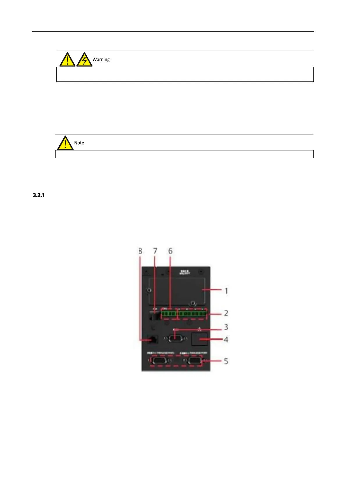
These functions are performed by the communication box in the UPS cabinet. As shown in Figure 3-6, the
communication box provides the following ports:
1.
Intellislot port
2.
Dry contact port
3.
RS232 port
4.
Ethernet port (not used)
5.
Parallel/LBS port
6.
REPO port
7.
USB port
8.
Multifunctional port
Figure 3-6 Illustration drawing of communication box ports
Prior to the service engineer's visit, if the load is not ready to be connected to the power supply, it is important to ensure the
terminals of the output cables are insulated safely