S600D
31
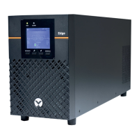
Figure 3-4 3-in 1-out, common input configuration cable connection (factory default)
2.
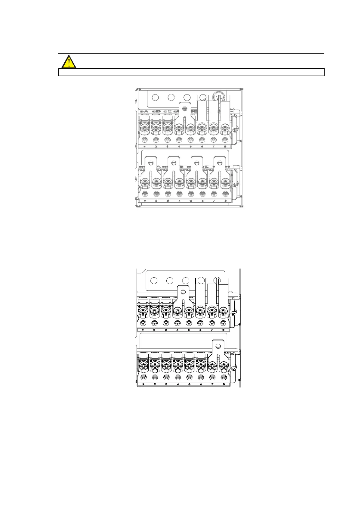
3-in 1-out, split bypass configuration
Refer to Figure 3-5, remove the three copper shorting bars between the rectifier input terminals (mA-mB-mC) and
the bypass input terminals (bA-bB-bC). Connect the rectifier input cables to the rectifier input terminals (mA-mB-
mC) in the cabinet, and connect the bypass input cables to the bypass input terminals (bA-bB-bC) in the cabinet.
Connect the input neutral line to the terminal N in the cabinet. Make sure that the phase rotation is correct.
Figure 3-5 3-in 3-out, split bypass configuration cable connection
3.
3-in 1-out, common input configuration
For more details, refer to 8.2.7 .
4.
3-in 1-out, split bypass configuration
For more details, refer to 8.2.7 .
Connecting the system output
In the case of 3-in 1-out configurations, connect the system output cables between the output terminals (oA-oB-oC-
oN) and the load; whereas, in the case of 3-in 1-out configurations, connect the system output cables between the