S600D
30
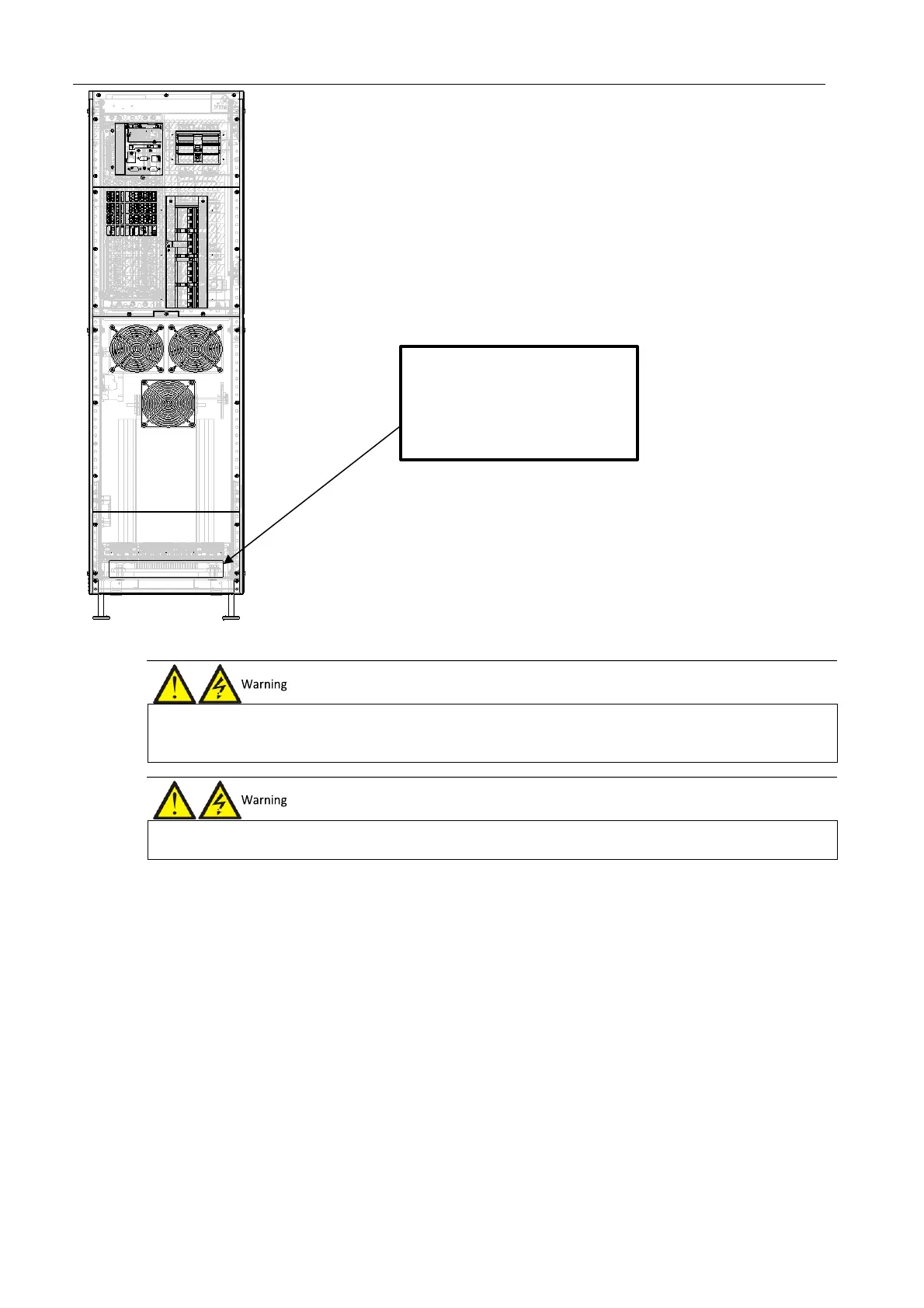
Figure 3-3 Power cables wiring diagram (rear cable access)
Power distribution mode
Based on the user's requirements, it is possible to select one of the following I/O cable connection configurations:
⚫
3-in 1-out, common input configuration
⚫
3-in 1-out, split bypass configuration
Connecting the system input
1.
3-in 1-out, common input configuration (factory default)
Refer to Figure 3-4, connect the AC input cables to the three copper shorting bars between the rectifier input
terminals (mA-mB-mC) and the bypass input terminals (bA-bB-bC) in the cabinet. Connect the input neutral line to
the terminal N in the cabinet. Make sure that the phase rotation is correct.
1.
Before connecting the cables, make sure that all the external and internal UPS power switches are set to OFF, and post the
appropriate warning signs to prevent inadvertent operation of the switches.
2.
Measure the voltages between the UPS terminals, and the voltages between the terminals and earth.
1.
The earth cables and neutral line must be connected in accordance with local and national codes of practice.
2.
Failure to observe this condition may result in electric shock or fire risk.
Remove this Panel,open holes
and lead cables through holes to
corresponding terminals