S600D
96
10.6
Electrical Specifications (Inverter Output)
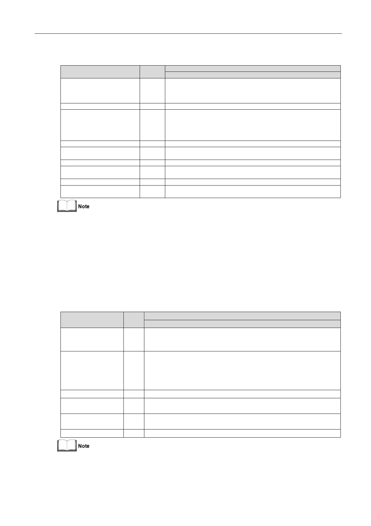
Table 10-6 Inverter output (to critical load)
220/230 (1-phase 2-wire, with neutral reference to the bypass neutral) (3-
in 1-out)
For linear load requirements:
< 105%, continuous;
105 - 125% of rated load, 5min;
125 - 150% of rated load, 1min;
> 150%, 200ms
Non-linear load capacity
3
Steady state voltage stability
±1% for balanced three phase load;
±2% for unbalanced load
Transient voltage response
4
±5% for 100% rated linear load step
2% (100% linear load);
5% (100% non-linear load)
Rated frequency ±0.5, ±1, ±2, ±3 (settable)
Slew rate (max. change rate of
synchronisation frequency)
Setting range: 0.2, 0.5, 1 (UPS module), 0.2 (parallel system)
1.
Factory set to 220V. 230V or 240V can be selected by service engineer at site.
2.
Factory set to 50Hz. 60Hz can be selected by service engineer at site. Note that the system frequency may only be changed
when the UPS is in bypass mode. It is strictly prohibited to change the system frequency when the UPS supplying the load via
the inverter.
3.
EN 50091-3 (1.4.58) crest factor 3:1, non-linear load.
4.
IEC/EN 62040-3/EN 50091-3 also for 0 - 100% - 0 load transient. Transient recovery time: returns to within 5% of steady state
output voltage within half a cycle.
10.7
Electrical Specifications (Bypass Input)
Table 10-7 Bypass input
220/230/240, 1-phase 2-wire, sharing neutral with the rectifier input and providing
neutral reference for the output, (3-in 1-out)
Based on nominal voltage and rated load current under apparent power:
< 105%, continues;
105 - 125% of rated load, 10min;
125 - 150% of rated load, 1min;
> 150%, 200ms
Upper limit: +10%, +15% or +20%, default: +20%;
Lower limit: -10%, -20%, -30% or -40%, default: -40%
Bypass frequency
tolerance
±5% or ±10%, default: ±10%
Rated frequency ±0.5, ±1, ±2, ±3, ±4, ±5 (settable); ±5 by default
1.
Factory set to 220V. 230V or V can be selected by service engineer at site.
2.
Factory set to 50Hz. 60Hz can be selected by service engineer at site.