S600D
33
Dry Contact Port
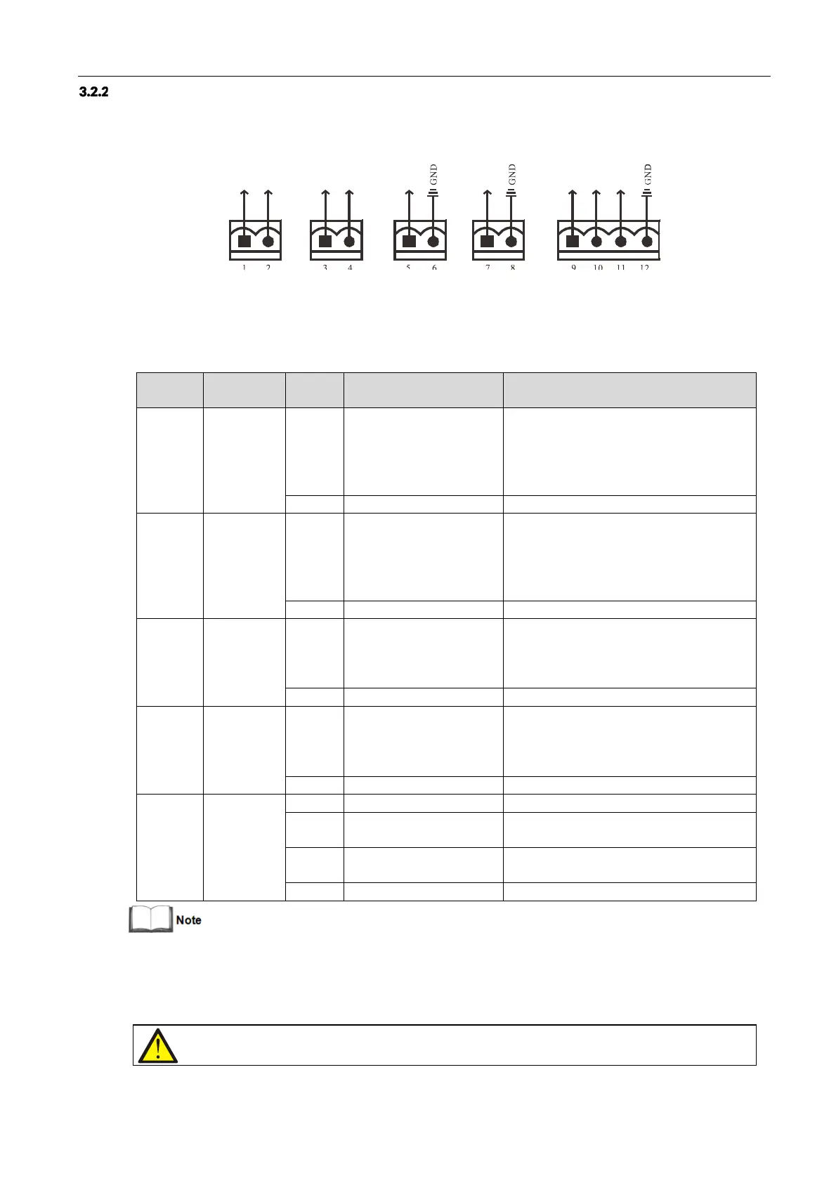
The UPS provides five dry contact ports. The silkprints of the five dry contact ports are
1
-
12.
The pin layout of each
dry contact port is shown in Figure 3-7, and the port description is shown in Table 3-5.
Figure 3-7 Pins of dry contact ports
Table 3-5 Description of the dry contact ports
LOW_BATTERY/ON_BATTE
RY
/ON_BYPASS/UPS_FAULT/
Main backfeed protection
enabled
Default: LOW_BATTERY, can be set-up via the
LCD settings page. Change main backfeed via
Paramset. When there is an alarm active on the
system, Pin 1 and Pin 2 are shorted together
LOW_BATTERY/ON_BATTE
RY
/ON_BYPASS/UPS_FAULT/
Bypass backfeed protection
enabled
Default: UPS_FAULT, can be set-up via the LCD
settings page. Change bypass backfeed via
Paramset. When there is an alarm active on the
system, Pin 3 and Pin 4 are shorted together
Battery mode shut-
down/Any mode shut-down
(Remote Comms Shut-
down)/ Maintain mode
Default: Maintain mode, can be set-up via the
LCD settings page. When Pin 5 and Pin 6 are
shorted together, the function is valid
Battery mode shut-
down/Any mode shut-down
(Remote Comms Shut-
down)/ Maintain mode
Default: Maintain mode, can be set-up via the
LCD settings page. When Pin 7 and Pin 8 are
shorted together, the function is valid
REPO power supply, 5Vdc 100mA
NC, ECO activated when there is an open circuit
between Pin 9 and Pin 10
REPO triggered when there is a short circuit
between Pin 11 and Pin 12
*: I/O dry contact port rating: 125 Vdc, 0.5 A; 30 Vdc, 1 A.
The terminals corresponding to Pin
11
and Pin 12 are reserved for configuring the REPO function. The REPO device
also requires a shielded cable for connecting the Normally Open remote REPO switch between the two terminals. If
not required, you should disconnect Pin 9 and Pin 10. Pin 9 and Pin 10 have been shorted together before delivery.
Note