Vertiv™ NetSure™ V200E50 DC Power Retrofit Installation and User Manual
Proprietary and Confidential © 2022 Vertiv Group Corp.
8. To return to the beginning of the MCA Logic Tree, press and release the FUNCTION SET YES (+) and NO (-) pushbuttons
simultaneously.
3.3 Remove Style Strips from Power Bay
Procedure
1. Remove the two style strips from the front left and right edges of the VPS Power Bay being upgraded. These conceal the
mounting hardware. The style strips are secured at the bottom with a captive fastener, and at the top with a pin that passes
through a hole in the style strip. To remove the style strip, loosen the captive fastener at the bottom, and slide the bottom of
the style strip out and up.
3.4 Remove the Power Conversion Unit (PCU) or Blank Cover Panel
Procedure
1. If the mounting position in the Power Bay has a cover panel rather than a V200 PCU, remove the cover panel by first
removing the four screws that secure it. Then skip steps 2 and 3.
NOTE!
In the next step, the OUTPUT SWITCH has a mechanical interlock that prevents a PCU from being plugged into or
pulled out of a bay with the device in the "on" position.
CAUTION! In a system with NO redundant Rectifier, battery must have sufficient reserve to power the load(s) while the
Rectifier is removed.
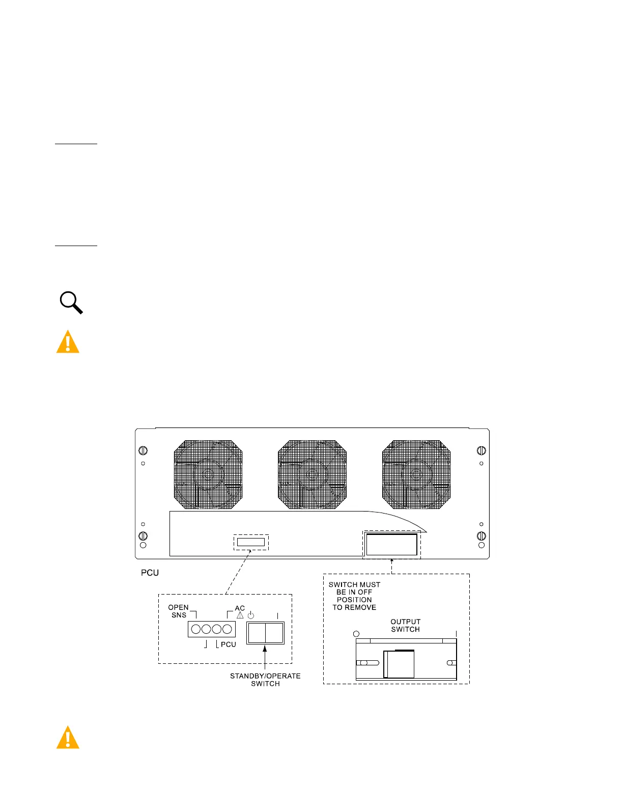
2. On the PCU to be removed, place the Standby/Operate switch to the "standby" position, then the OUTPUT SWITCH to the 0
"off" position. See Figure 3.1 for locations.
Figure 3.1 Switch Locations
DANGER! In the next step, use two people to remove a PCU. A PCU weighs approximately 80 lbs.