Vertiv™ NetSure™ V200E50 DC Power Retrofit Installation and User Manual
Proprietary and Confidential © 2022 Vertiv Group Corp.
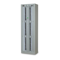
5.2 Replacement Procedures
5.2.1 Replacing a Rectifier
DANGER! Use caution when removing a Rectifier that has been operating, as Rectifier surfaces could be very hot.
WARNING! In order to prevent damage to the latching mechanism, do not use excessive force on the Rectifier handle when
pushing the Rectifier into the Mounting Frame.
CAUTION! In a system with NO redundant Rectifier, battery must have sufficient reserve to power the load(s) while the
Rectifier is removed.
Rectifiers can be inserted or removed with power applied (hot swappable).
Procedure
1. Performing this procedure may activate external alarms. Do one of the following. If possible, disable these alarms. If these
alarms cannot be easily disabled, notify the appropriate personnel to disregard any future alarms associated with this system
while this procedure is being performed.
2. Remove the front cover panel from the Mounting Frame by first loosening two captive fasteners. Refer to Figure 3.7.
3. THIS STEP MUST BE PERFORMED WITH THE “SAFETY LATCH RELEASE” IN THE DOWN (LOCKED) POSITION. On the
Rectifier to be removed, loosen the captive fastener (located on the Rectifier’s handle) securing the Rectifier to the Mounting
Frame. Pull the handle out, and gently pull the Rectifier out until it stops. The Rectifier CANNOT be completely removed
until the next step is performed. Refer to Figure 3.8 for an illustration.
4. Push the “Safety Latch Release” located on the front of the Rectifier UP. Slide the Rectifier completely out of the Mounting
Frame.
5. Place the new Rectifier into its mounting position in the Mounting Frame without sliding it in completely.
6. Push the “Safety Latch Release” located on the front of the Rectifier UP. Refer to Figure 3.8 for an illustration.
7. Gently push the Rectifier into the Mounting Frame until it stops. Note that the Rectifier will NOT be completely seated in the
Mounting Frame until the next step is performed.
8. Push the “Safety Latch Release” located on the front of the Rectifier DOWN. Gently push the Rectifier into the Mounting
Frame until it is completely seated.
9. Push the Rectifier handle in and secure the Rectifier to the bay by tightening the captive fastener located on the handle.
10. After the Rectifier is physically installed in the Mounting Frame, it is ready for operation immediately after power is supplied
to it. Verify that the Rectifier is operating normally.
11. On the Power System controller (MCA), update the system inventory as necessary. Refer to the Power System
documentation for a procedure.
12. Ensure that there are no local or remote alarms active on the system.
13. Install the front cover on the Mounting Frame. Secure by tightening the two captive fasteners. Refer to Figure 3.9.
5.2.2 Replacing the Rectifier Interface Circuit Card
One Rectifier Interface Circuit Card, Part No. 547568, is located within the V200 Retrofit Mounting Frame. To replace this circuit card
perform the following procedure.