Vertiv™ NetSure™ V200E50 DC Power Retrofit Installation and User Manual
Proprietary and Confidential © 2022 Vertiv Group Corp.
Mounting Procedure
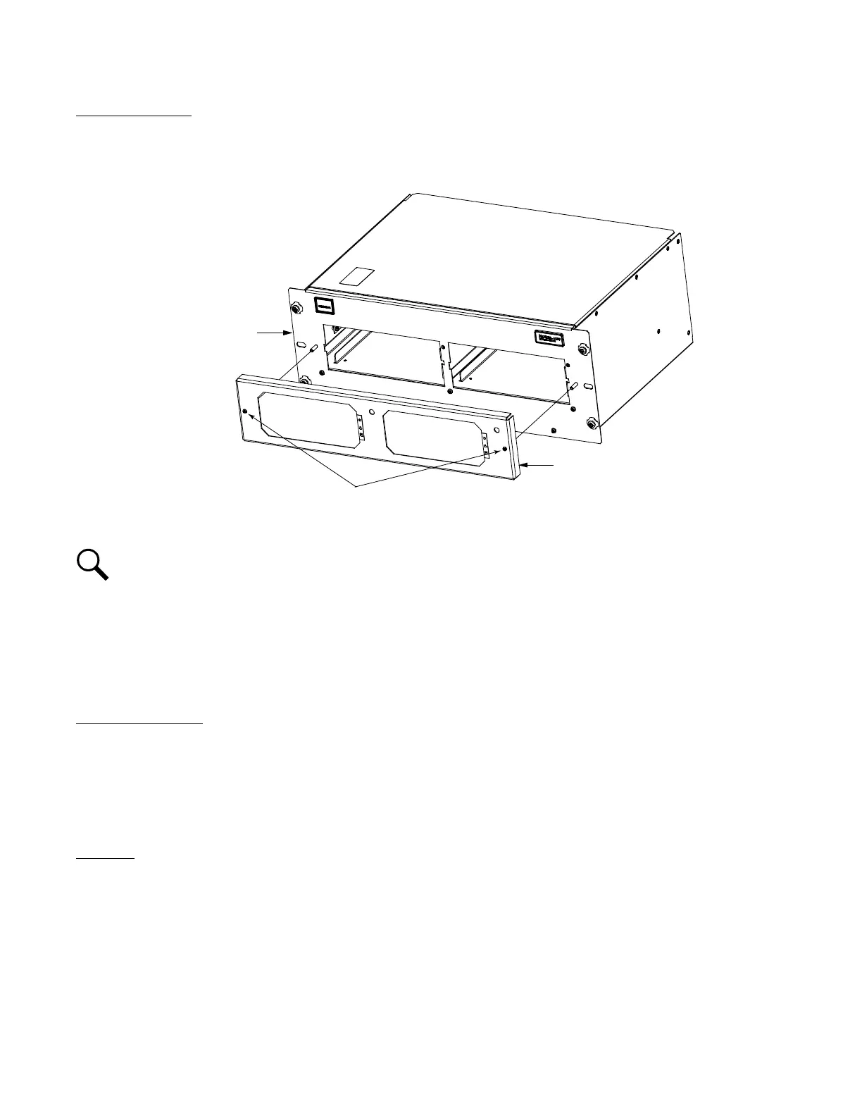
1. Remove the front cover panel from the Mounting Frame by first loosening two captive fasteners. Refer to Figure 3.7.
Figure 3.7 Removing the Cover Panel from the Mounting Frame
NOTE!
In the next step, the Mounting Frame CANNOT be installed in the Power Bay unless all Rectifiers are first
removed from the Mounting Frame. Doing so will defeat the precharge circuit in the rectifiers and cause arching and
pitting on the DC power connector!
2. Ensure no Rectifiers are present in the Mounting Frame.
3. Slide the empty Mounting Frame into an open mounting position in the Power Bay.
4. Using the hardware supplied, secure the Mounting Frame to the Power Bay.
Electrical Connections
All electrical connections to the Mounting Frame are made automatically when the Mounting Frame is installed in the Power Bay. No
additional connections are required.
3.6 Install the Rectifiers
Procedure
1. Place one Rectifier into an unoccupied mounting position in the Mounting Frame without sliding it in completely.
2. Push the “Safety Latch Release” located on the front of the Rectifier UP. Refer to Figure 3.8 for an illustration.
Mounting Frame
Front Cover Panel
Captive Fasteners