Vertiv™ NetSure™ V200E50 DC Power Retrofit Installation and User Manual
Proprietary and Confidential © 2022 Vertiv Group Corp.
NOTE!
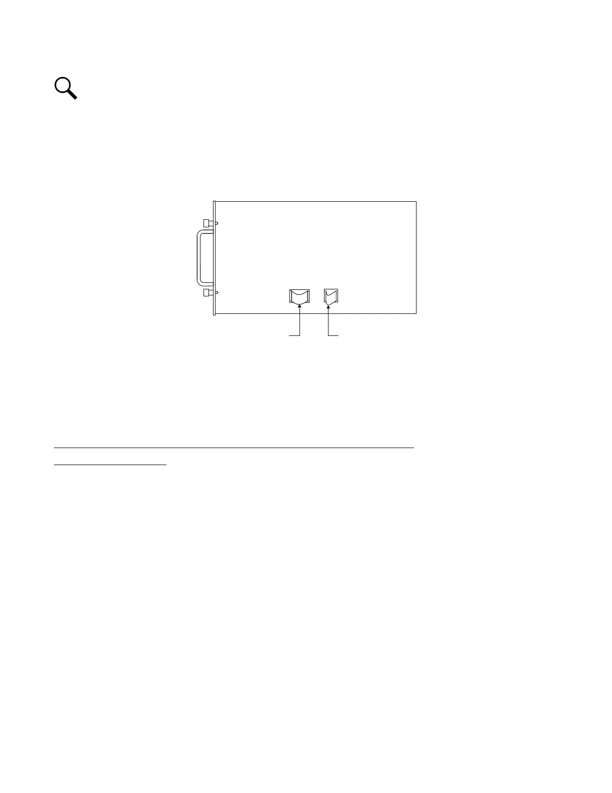
In the next step, a safety latch is present on each PCU that prevents the PCU from inadvertently being removed
completely from the Power Bay.
3. Loosen the captive fasteners on the front of the PCU to be removed. Use the handles provided on the front of the PCU, and
pull the PCU out until it is stopped by a safety latch located on the right-hand side panel of the PCU. Refer to Figure 3.2 for
latch and release location. Depress and hold the latch release, and remove the PCU from the Power Bay. Support the bottom
of the PCU as you pull it out.
Figure 3.2 Right Side View of V200 PCU Showing Location of Safety Latch and Latch Release
3.5 Install the Mounting Frame
The Retrofit Mounting Frame CANNOT be installed in the Power Bay unless all Rectifiers are first removed from the Mounting
Frame. Doing so will defeat the precharge circuit in the rectifiers and cause arching and pitting on the DC power connector!
Checking the Power Bay’s Rectifier AC/Data Connector in Older Style Bays
Identifying Older Style Bays
1. Older style bays have Rectifier AC/Data connectors that do not have springs as shown in Figure 3.3. In bays that have
Rectifier AC/Data connectors without springs, perform the following procedure.