Vertiv™ NetSure™ V200E50 DC Power Retrofit Installation and User Manual
Proprietary and Confidential © 2022 Vertiv Group Corp.
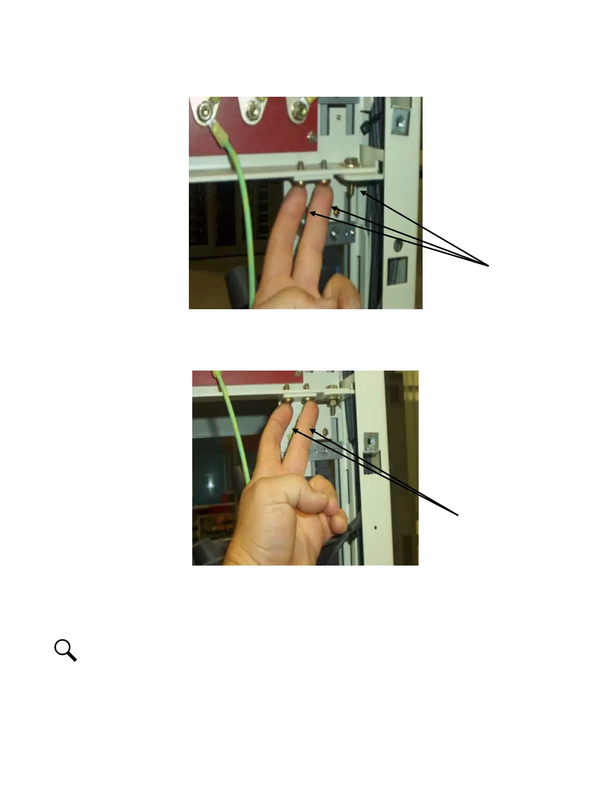
Figure 3.5 Locating the Bottom Two 1/4” Self Tapping Screws and 1/4” Hex Bolt
4. Next loosen the two Philips 1/4” self tapping screws at the top of the PCU position to be adjusted. See Figure 3.6.
Figure 3.6 Locating the Top Two 1/4” Self Tapping Screws
5. With hardware loosened, measure the bottom first for a 15-5/16” and secure the single 1/4” hex bolt first.
6. With bottom secured at 15-5/16”, move to the top of the AC connector and measure for 15-5/16”, then secure the two Philips
screws at the top of the back plane sheetmetal.
NOTE!
The process of measurement and securing the hardware may take two people to keep the panel from moving when
retorqueing the hardware.
7. Torque the top and bottom 1/4” screws (2 each) and bottom 1/4” bolt to 84 in-lbs.
8. Recheck the measurements by performing the previous procedure to verify the proper measurements.
 Loading...


