Vertiv™ NetSure™ V200E50 DC Power Retrofit Installation and User Manual
Proprietary and Confidential © 2022 Vertiv Group Corp.
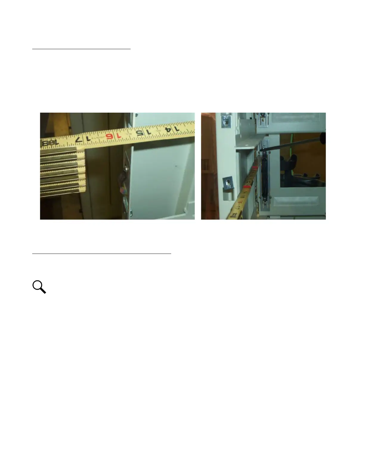
Check Procedure (Older Style Bays Only)
1. With the PCU removed, use a quality wooden carpenter’s ruler or other non-conductive rule. Place the measuring device
directly against the unpainted bracket holding the AC/Data connector. Take two measurements, one on the bottom of
connector directly next to the bolt through the black ac housing, and note the distance to the front outside of the left side
panel. Take second measurement on the top of the AC/Data connector. Both must measure 15-5/16” + 1/16” or -1/16”
tolerance. See Figure 3.4.
Figure 3.4 Taking Measurements
2. Pay close attention to the measurements, they must be within 15-1/4” to 15-3/8”. If a measurement is greater than 15-3/8” or
less than 15-1/4”, adjustment is required (see next procedure).
Adjustment Procedure (Older Style Bays Only, if required)
1. When adjustment of the PCU slot is required, it is recommended to remove the PCU below the slot which requires
adjustment. This allows the AC/Data connector to be moved as required to properly set the 15-5/16” measurements.
NOTE!
The MCA will alarm with the removal of any PCU, so be aware Minor and Major alarms could be generated during this
process.
2. In the PCU slot to be adjusted, remove the rear sheet metal panel on the rear of bay and locate the two Philips 1/4” self
tapping screws at the bottom of panel, which holds the AC connector. Loosen these screws. See Figure 3.5.
3. Directly to the right of the two Philips screws is a single 1/4” inch hex bolt which also must be loosened for lower adjustment.
See Figure 3.5.