Chapter 3 Web Interface of RDU501
RDU501 Intelligent Monitoring Unit User Manual
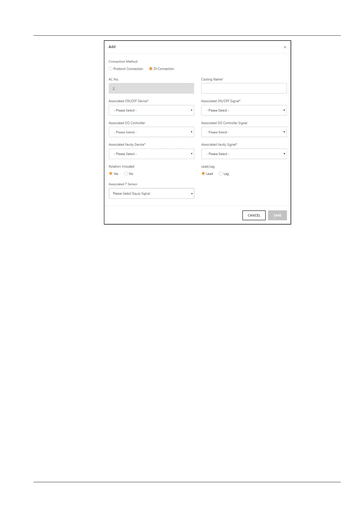
Figure 3-63 Add / modify air conditioner page (DI connection)
Procedures for adding air conditioner:
1)
In the Air conditioner index bar, enter the index of the air conditioner in the group (the default index will be
increased from 1);
2)
Select the air conditioner that needs teamwork control from the air conditioner drop-down box, and fill it only in the
protocol connection;
3)
Check whether to participate in the rotation schedule;
4)
Select the device with DO from the Associated DO controller (optional);
5)
Select the signal corresponding to the DO device from the Associated DO controller signal drop-down box
(optional);
6)
Select the active and standby properties to specify the current active and standby properties of the air conditioner.
This attribute will change. For example, if the A air conditioner is currently set as the host, when the rotating time is
reached, the attribute of the air conditioner A will become the standby unit.
7)
Set the Associated temperature sensor, each air conditioner can be connected with up to 5 temperature
sensors. When the highest temperature in the associated sensor is higher than the air conditioner startup
temperature, if the current running state of the air conditioner is off, the air conditioner will be started. When the
maximum temperature is lower than the air conditioner shutdown temperature, if the current running state of the air
conditioner is running, the air conditioner will be turned off.
8)
Set the air conditioner fault alarm signal which are generated if the air conditioner is faulty or unavailable. A
maximum of 15 fault alarm signals are allowed for each air conditioner.
9)
In the Air Conditioner Name field, enter the name of the air conditioner in the teamwork control and fill it only in
the DI connection;
10)
Select the switch device to be associated in the drop-down box of the Associated Switch Device, and select
only in the DI access;
11)
Select the signal of the associated switch device in the Associated Switch Device Signal drop-down box, and
select only in the DI access;
12)
Select the fault status device to be associated in the Associated Fault Status Device drop-down box and select
only in the DI access;


 To Next Page