Chapter 1 Product Introduction
RDU501 Intelligent Monitoring Unit User Manual
Input power
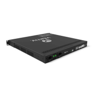
There are two isolated power inputs on the rear panel of the RDU501 main unit. The location is shown in Figure 1-1.
The power input parameters are shown in Table 1-1.
Table 1-1 Power input parameters
AC Input
C14 with break-away prevention feature
Indicators
The rear panel of the RDU501 has four indicators. The location is shown in Figure 1-1. See Table 1-2 for definitions.
Table 1-2 Definitions of rear panel indicator
Power1 Green
RDU501 power supply 1 is on
RDU501 power supply 1 is off
Power2 Green
RDU501 power supply 2 is on
RDU501 power supply 2 is off
Link Green
Wrong connection or disconnected
Speed Yellow
Figure 1-1 shows the positions of the indicators on the front panel of the RDU501 main unit. See Table 1-3 for
definitions.
Table 1-3 Definitions of front panel indicator
Run/Alarm Green /Red
COM/Sensor
Green
Yellow
DI/AI/DO/AO/Smoke Green
External device is connected
No external device is connected or the port is short circuited
Reset button
Press and hold the reset button (Silk Screen Printing is “Reset”) for more than 4 seconds. After the device emits a
“beep” sound, the RDU501 will restore the IP address and password to the factory default after it is restarted. The
default values are shown in Table 1-4.
USB port
The RDU501 main unit provides four ports of USB-A socket type, which can be connected to the USB Modem of the
specified model, as well as the keyboard and mouse. The location is shown in Figure 1-1.
Ethernet port
The RDU501 main unit provides two network ports and one fiber port. The 10/100/1000M Ethernet port is used.
Figure 1-1 shows the 1000M fiber. Table 1-4 lists the default network port configuration.
Table 1-4 Network port default configuration parameters
Network card number
IP address Subnet code Default gateway
(
(
Note: The default password for terminal background and web browser login is “Vertiv”