Chapter 1 Product Introduction
RDU501 Intelligent Monitoring Unit User Manual
Relay output port
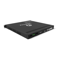
The RDU501 main unit provides two relay output ports DO1 and DO2. The position is shown in Figure 1-1. The
parameters are shown in Table 1-5.
Table 1-5 Parameters of relay output ports
DO1/DO2
RJ45
1. DO output, can be connected to the alarm indicator;
2. The maximum total power of the two ports can support 2.4W;
3. Support short circuit protection
Total current ≤0.2A
DI port
The RDU501 main unit provides four digital input ports, as shown in Figure 1-1. The parameters are shown in
Table 1-6.
Table 1-6 Electrical parameters of DI port
Printing
Definition
Voltage
(Total)
(Total)
Protection
DI1
switch 1
9V~12.5V
<0.16A
1.92W
Support overload
protection
DI2
switch 2
Smoke1
1
Smoke2
2
Sensor port
The RDU501 main unit provides two sensor ports, including four RJ45 interfaces. The location is shown in Figure 1-1.
The parameters are shown in Table 1-7.
Table 1-7 Electrical parameters of sensor port
Printing
Definition
Voltage
(Total)
(Total)
Protection
Sensor1
sensor
9V~12.5Vdc
<0.36A
4.32W
Support overload
protection
Sensor2
sensor
The port adopts RS-485 communication mode for connecting Vertiv intelligent temperature and humidity sensor,
intelligent temperature sensor and intelligent digital expansion sensor. The communication parameters are shown in
Table 1-8.
Table 1-8 Communication parameters of sensor port
Serial port
The RDU501 main unit provides four independent serial ports: serial port 1, serial port 2, serial port 3, and serial port
4. The location is shown in Figure 1-1. The interface adopts RS-485/232C (self adaptive) communication mode, and
the communication parameters are shown in Table 1-9.
Table 1-9 Serial port communication parameters
Note: The combination of 5-bit word length and 2 stop bits is not supported.