Chapter 3 Web Interface of RDU501
RDU501 Intelligent Monitoring Unit User Manual
For the usage of each operator in alarm linkage, see Table 3-4.
Table 3-4 Alarm linkage operator usage
AND Sin1 /Rin1 Sin2 /Rin2 / / Sout/Rout
Sin1 [Rin1] AND Sin2 [Rin2]
=
[Rout]
OR Sin1 /Rin1 Sin2 /Rin2 / / Sout/Rout
Sin1 [Rin1] OR Sin2[Rin2]
=
[Rout]
=
XOR Sin1 /Rin1 Sin2 /Rin2 / / Sout/Rout
Sin1 [Rin1] XOR Sin2[Rin2]
=
[Rout]
GT Sin1 /Rin1 / P1 P2 Sout/Rout
Sin1 [Rin1]>P1, Sout [Rout]
=
Sin1 [Rin1]<P1-P2, Sout [Rout]=0
LT Sin1 /Rin1 / P1 P2 Sout/Rout
Sin1 [Rin1]<P1, Sout [Rout]
=
Sin1 [Rin1]>P1+P2, Sout [Rout]=0
DS Sin1 /Rin1 / P1 / Sout/Rout
Sin1 [Rin1] DS P1 output to Sout
[Rout]
1. Sin1, Rin1, Sin2, Rin2, P1, P2, Sout, Rout respectively refer to signal 1, input 1 register, signal 2, input 2 register, parameter 1,
parameter 2, signal 3, output register;
2. The input signal of the logical operator AND/OR/NOT/XOR/DS can only select the alarm signal;
3. The input signal value of the arithmetic operator GT/LT can only be floating point, integer or long integer;
4. The output signal can be a control signal or a set signal
The following is an application example of alarm linkage.
Example 1:
If the temperature and humidity sensor 01 of the RDU501 system needs to be connected to the temperature and
humidity sensor of the RDU501 system, the alarm indicator will be illuminated. If the alarm indicator is installed on the
DO1 interface, you can complete the alarm linkage function through the following configurations.
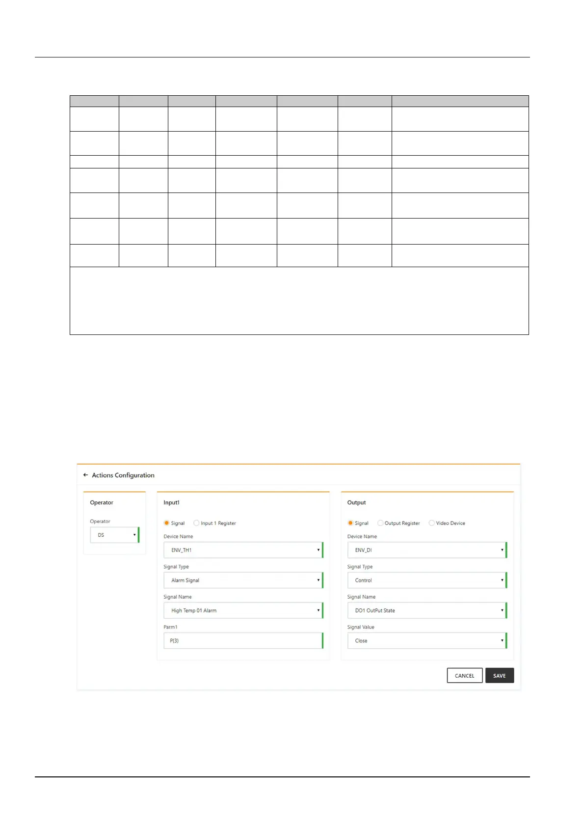
Expression: [Temperature 01 High Temperature Alarm] DS P(3) [DO1][Closed]
Figure 3-131 shows the configuration method. The meaning is that when the temperature 01 generates a high
temperature alarm, the DO1 is turned off after a delay of 3 seconds, thereby lighting the alarm indicator.
Example 2:
Figure 3-131 Configuration example of alarm linkage 1
If the front or rear door of the cabinet is open, the alarm indicator is illuminated. Assume that the DI1 and DI2
interfaces of the RDU501 are connected to the front and rear door magnetic sensors of the cabinet. The alarm
indicator are installed on the DO1 interface. You can use following method to complete the configuration:


 To Next Page